
Solenoid valve

a solenoid valve and valve body technology, applied in the direction of valve operating means/releasing devices, mechanical equipment, transportation and packaging, etc., can solve the problems of troublesome control of the attitude of the coil assembly, the inability of the coil assembly to be positioned in the magnetic cover in a straight angle, etc., and achieve the effect of simplifying the assembly job

Active Publication Date: 2008-05-27
SMC CORP
View PDF17 Cites 12 Cited by
  • Summary
  • Abstract
  • Description
  • Claims
  • Application Information

AI Technical Summary

Benefits of technology

This design simplifies the assembly process by allowing the coil assembly to be inserted straight, reduces the need for additional sealing, and maintains the magnetic path area, enhancing workability and safety.

Problems solved by technology

However, when the coil terminals extend from a side surface of the coil assembly in the direction perpendicular to the axial line as described above, the coil assembly cannot be accommodated in the magnetic cover in a straight attitude.
However, when the terminal insertion holes are formed excessively large, the exciting coil is exposed to the outside through the terminal insertion holes.
Thus, when an assembly job is automatically carried out by a robot, it is troublesome to control the attitude of the coil assembly.

Method used


Image

  • Solenoid valve
  • Solenoid valve
  • Solenoid valve

Examples


second embodiment

[0044]Otherwise, as in a second embodiment shown in FIG. 5, the interior of the protection cover 45 is filled with a potting member 60 composed synthetic resin such as epoxy resin or the like, and the potting member 60 may be provided with a function for adhering and fixing the protection cover 45 to the magnetic cover 30 and a function for electrically insulating between the magnetic cover 30 and the print board 44, and the power receiving terminals 50. When the protection cover 45 is filled with the potting member 60, the joint portions of the protection cover 45 and the magnetic cover 30 are tentatively adhered to each other with an instant adhesive as well as a seal agent is applied to the entire peripheries of the joint portions to prevent the potting member in a melted state from protruding from them, the interior of the protection cover 45 is filled with the potting member 60, and the potting member 60 is solidified.

first embodiment

[0045]Note that the potting member 60 can be used together with the fixing method using the screws or the fixing method using the elastic locking pieces or the adhesive as shown in the

[0046]Although the illustrated solenoid valve is a poppet type three-port valve, the switching system and the number of ports of the solenoid valve are not limited to those shown above. That is, the switching system may be a spool system, and the number of the ports may be two ports, four ports, or five ports.


PUM


Abstract

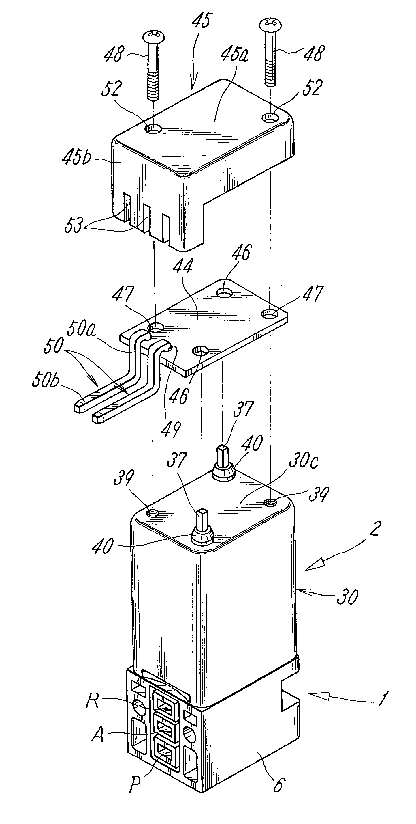
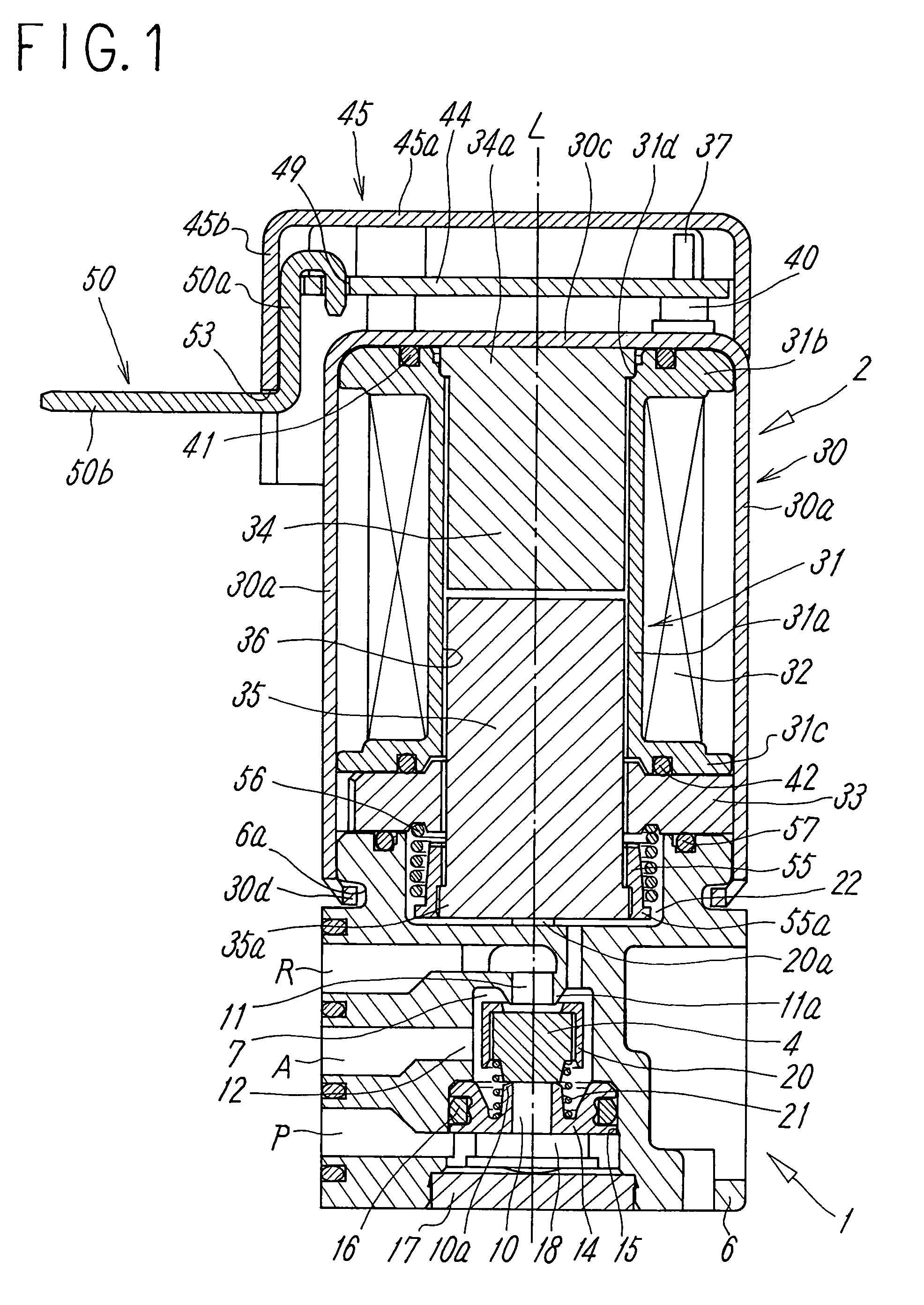
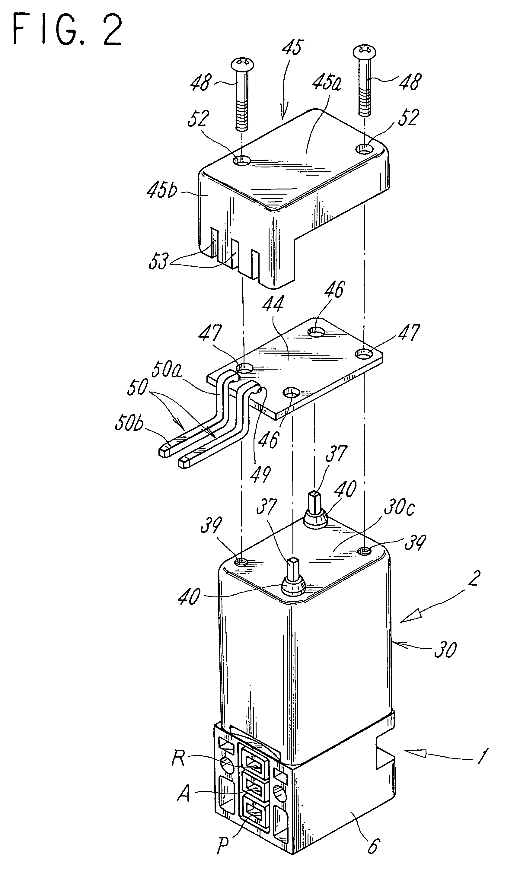
A pair of terminal insertion holes are formed to the end wall portion of an magnetic cover in an electromagnetic manipulator, a pair of coil terminals electrically conductive to an exiting coil are extended from a first flange portion of a bobbin in parallel with the axial line of the bobbin as well as extended to the outside of the end wall portion passing through the terminal insertion holes in an electrically insulated state due to the interposition of rubber bushes, a print board electrically connected to the coil terminals and an electrically insulating protection cover for covering the print board are disposed above the outside surface of the end wall portion, and power receiving terminals to which a power supply external connector is connected are disposed to the print board.

Description

TECHNICAL FIELD[0001]The present invention relates to a solenoid valve arranged by coupling a main valve portion having a valve member for switching a flow path with an electromagnetic manipulator for manipulating the valve member along an axial line.BACKGROUND ART[0002]The following patent documents 1 and 2 disclose linear moving type solenoid valves each formed by coupling a main valve portion having a valve member for switching a flow path in series with an electromagnetic manipulator for manipulating the valve member along an axial line.Patent document 1: Japanese Utility Model Application Publication No. 5-18537Patent Document 2: Japanese Unexamined Patent Application Publication No. 2001-116162[0003]In these solenoid valves, the electromagnetic manipulator has a rectangular cylindrical magnetic cover having one end closed and the other end opened, a hollow bobbin accommodated in the magnetic cover, an exciting coil wound around the bobbin, a fixed iron core and a movable iron ...

Claims


Application Information

Patent Timeline
Patent Type & Authority Patents(United States)
IPC IPC(8): F16K31/12
CPCF16K31/0603F16K31/0693Y10T137/87885
Inventor NARITA, MASARUSATO, HIDEHARU
Owner SMC CORP
Learn More