Magnetic encoder

a technology of magnetic encoder and encoder, which is applied in the field of magnetic encoder, can solve the problems of low electric power consumption, reduced electric resistance of elements, and difficult use, and achieves the effects of less electric power consumption, large magneto-resistance variation ratio, and large electric resistan

Inactive Publication Date: 2008-05-27
HITACHI METALS LTD
View PDF12 Cites 13 Cited by
  • Summary
  • Abstract
  • Description
  • Claims
  • Application Information

AI Technical Summary

Benefits of technology

[0010]An object of the present invention is to provide a magnetic encoder, which comprises a magnetic sensor composed of SVGMR elements and a magnetic medium that has successively magnetizations alternately magnetized in opposite directions, that provides an electric signal having a cycle of a half of a magnetized region cycle of the magnetic medium, a low electric power consumption in the magnetic encoder and a stable output property with respect to a gap variation.
[0028]Further, in the magnetic encoder of the present invention, it is preferable that each of the first and the second sensors is composed of more than four SVGMR elements. When each of the first and the second sensors is composed of four SVGMR elements, each of the first and the second sensors can simultaneously detect magnetic fields caused from two successive first / second magnetized regions. And, when each of the first and the second sensors is composed of 2n SVGMR elements (n: a positive integer), each of the first and the second sensors can simultaneously detect magnetic fields caused from n successive first / second magnetized regions. Since each of the first and the second sensors can simultaneously detect magnetic fields from n successive first / second magnetized regions, outputs from the first and the second sensors are caused from an average of magnetic fields of the n first / second magnetized regions so that variations in length or magnetic strength in the n successive first / second magnetized regions can be compensated. As a result, a zitter in signal output can be reduced.
[0030]According to the present invention, an electric signal of a cycle λthat is an average length of each magnetized region has been accomplished by a magnetic encoder having SVGMR elements. Also, since SVGMR elements of large electric resistance are used, a magnetic sensor of less electric power consumption has been realized. Furthermore, a large magneto-resistance variation ratio has been obtained in a region of relatively small magnetic field, and a magnetic encoder capable of obtaining a stable output property (gap property) against a variation of a gap between a magnetic sensor and a magnetic medium has been realized.

Problems solved by technology

Further, low electric power consumption is required.
But, they are difficult to use, since electric resistance of the elements reduces due to the thicker film.
Because of the reason, it was difficult to enhance the resolution in a magnetic encoder using AMR elements.
However, it is difficult to accomplish a low electric power consumption, since the non-magnetic metal thin films are a good electrically conductive material and the electric resistance of the film is as low as a half to a third of that of an AMR element.
By the reason, it was hard to use them in a relatively small magnetic field as in a magnetic encoder.
However, a magnetic encoder has a disadvantage that resolution is reduced by only a substitution of the SVGMR elements for AMR elements and coupled GMR elements.
This is caused by a magneto-resistance variation characteristic, and the reduction in the resolution cannot be avoided in a conventional encoder structure.
SVGMR elements have not been applied to a magnetic encoder because they hardly satisfy a high resolution that is demanded in a market.
However, since the SVGMR elements show a magneto-resistance variation ratio as much as in coupled GMR elements in a region of a relatively small magnetic field and also an electric resistance as large as five times to six times that of the coupled GMR elements, it is hard to give up an advantage that a low electric power consumption can be easily accomplished by the SVGMR elements.

Method used


Image

  • Magnetic encoder
  • Magnetic encoder
  • Magnetic encoder

Examples


example 1

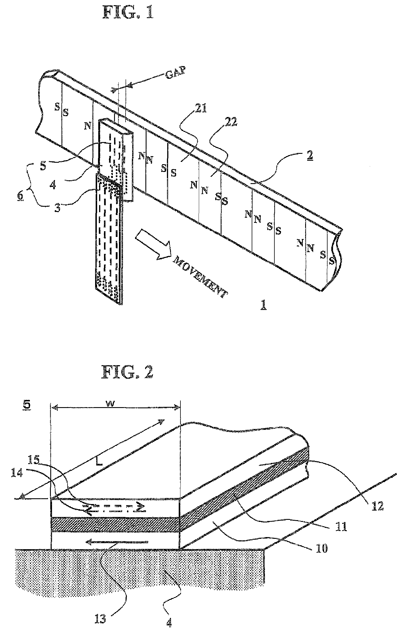
[0043]FIG. 1 shows a perspective schematic view for explaining a magnetic encoder having SVGMR elements. The magnetic encoder 1 is composed of a magnetic medium 2 and a magnetic sensor 6. On the magnetic medium 2, two magnetized regions, that is, first magnetized regions 21 and second magnetized regions 22, which are magnetized oppositely to each other, are arranged successively and alternately along the medium extending. In the following explanation, it is presumed that the length λl of the first magnetized regions 21 is longer than the length λs of the second magnetized regions 22. In the magnetic sensor 6, plural SVGMR elements 5 are formed in rectangular flat surfaces extending perpendicularly to the magnetic medium 2 extending on a base material 4, and ends of the SVGMR elements 5 are connected through lead wires (not shown) to a flexible print circuit 3. The magnetic medium 2 faces the SVGMR elements 5 having rectangular flat surfaces with a predetermined gap. When the magneti...

example 2

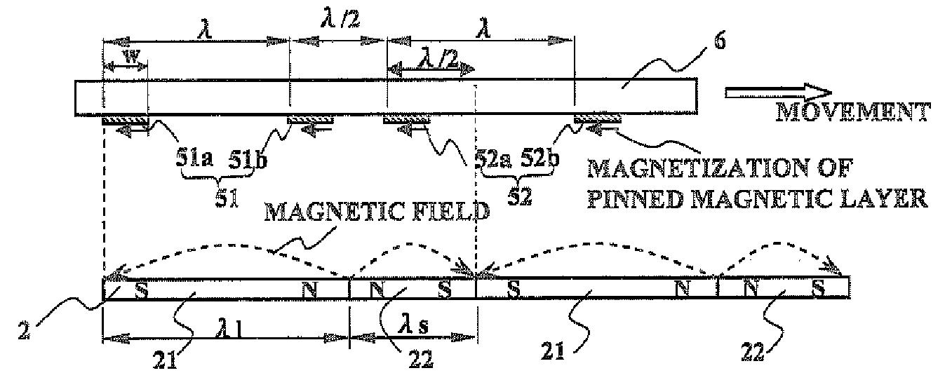
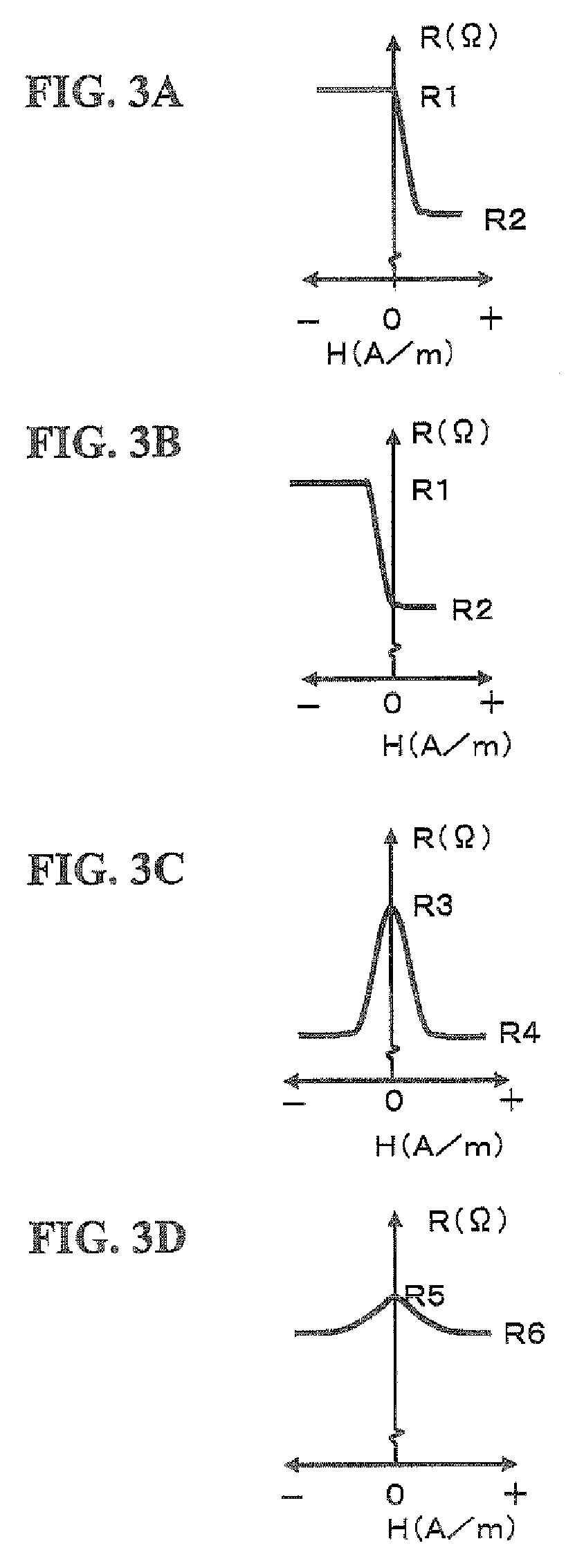
[0047]Referring to FIG. 4, in which a first magnetized region length λl is longer than a second magnetized region length λs on a magnetic medium 2, a work of a magnetic encoder will be described. FIG. 4A explains a location relationship between SVGMR elements 51a to 52b of a magnetic sensor 6 and the magnetic medium 2, and FIGS. 4B to 4F show graphs of electric resistances and an electric signal with respect to a location on the magnetic medium 2 where the SVGMR elements 51a to 52b are. Electric resistance graphs of an SVGMR element 51a of a first sensor 51, another SVGMR element 51b of the first sensor 51, the first sensor 51 composed of the SVGMR elements 51a and 51b, a second sensor 52 composed of SVGMR elements 52a and 52b are shown in FIGS. 4B, 4C, 4D and 4E, respectively. In the magnetic sensor 6, the four SVGMR elements 51a to 52b are disposed on a base material. Each of the SVGMR elements has an element width w, and an SVGMR element is at a distance λ from another in each of...

example 3

[0052]Referring to FIGS. 6A to 6F, a magnetic encoder of EXAMPLE 3 will be described, which is similar to a magnetic encoder of EXAMPLE 2 shown in FIG. 4A with an exception that a magnetic medium 2 has a first region length shorter than a second magnetized region length. FIG. 6A explains a location relationship between SVGMR elements 51a to 52b of a magnetic sensor 6 and the magnetic medium 2, and FIGS. 6B to 6F show graphs of electric resistances and an electric signal with respect to a location on the magnetic medium 2 where the SVGMR elements 51a to 52b are. Electric resistance graphs of an SVGMR element 51a of a first sensor 51, another SVGMR element 51b of the first sensor 51, the first sensor 51 composed of the SVGMR elements 51a and 51b, a second sensor 52 composed of SVGMR elements 52a and 52b are shown in FIGS. 6B, 6C, 6D and 6E, respectively. In the magnetic sensor 6, the four SVGMR elements 51a to 52b are disposed on a base material. Each of the SVGMR elements in each sen...


PUM


Abstract

A magnetic encoder having a magnetic sensor composed of SVGMR elements, in which a signal output with a half of a cycle of magnetic regions on a magnetic medium. The magnetic encoder comprises the magnetic medium, on which first magnetic regions and second magnetic regions are oppositely magnetized along the medium extending and disposed successively and alternately with each other, and the magnetic sensor that has an even number of SVGMR elements and is movable relatively to the medium along the medium extending. Magnetizations of pinned magnetization layers of all the SVGMR elements are directed in a same direction along the medium extending. Each of the even number of SVGMR elements in the magnetic sensor is apart by a half of the sum of a first magnetic region length plus a second magnetic region length from each other along the medium extending, and the even number of SVGMR elements are connected in series so that a cycle of resistance change of the magnetic sensor is a half of a cycle length of the first and the second magnetic regions on the medium and the signal output with high resolution can be obtained.

Description

BACKGROUND OF THE INVENTION[0001]1. Field of the Invention[0002]The present invention relates to a magnetic encoder using a magnetic sensor with a spin-valve type giant magneto-resistance effect film.[0003]2. Description of the Related Art[0004]In recent years, a magnetic encoder applied to civil appliances, such as small-sized robots, digital cameras and ink-jet printers, is required not only to be cheap and small-sized but also to have a high resolution and excellent gap output characteristics. In other words, it is required that a magnetic encoder is small-sized but does not need a processing circuit for doubling frequency of signal and also can maintain a stable output against gap variation during its operation. Further, low electric power consumption is required.[0005]In a conventional magnetic encoder, magnetic resistors formed from an anisotropic magneto-resistance effect film (hereinafter referred to as “AMR element”) are applied. The AMR elements are widely used, because el...

Claims


Application Information

Patent Timeline
Patent Type & Authority Patents(United States)
IPC IPC(8): G01B7/14
CPCG01D5/145G01B7/14
Inventor ABE, YASUNORINIHEI, YUJI
Owner HITACHI METALS LTD
Why Eureka
Try Eureka