Low jitter phase rotator

a rotator and phase jitter technology, applied in the field of multiple clock apparatus, can solve the problems of data loss, user inconvenience, data loss during compression, etc., and achieve the effect of reducing jitter

Inactive Publication Date: 2008-05-27
AVAGO TECH INT SALES PTE LTD
View PDF15 Cites 11 Cited by
  • Summary
  • Abstract
  • Description
  • Claims
  • Application Information

AI Technical Summary

Benefits of technology

[0009]The present invention is a phase rotator that generates an output signal havin...

Problems solved by technology

When data is compressed using MPEG, some of the data is lost during the compression.
Such loss of data may be attributed to different factors such as variation of components in the system, signal jitter and others.
A user is often inconvenienced by having to wait until recording of the MPEG-coded data finishes in order to do something else with the d...

Method used


Image

  • Low jitter phase rotator
  • Low jitter phase rotator
  • Low jitter phase rotator

Examples


Embodiment Construction

Table of Contents

[0029]1. Overview[0030]2. Phase Locked Loop Circuit[0031]3. Multiple Synthesized Clocks with Fractional PPM Control from a Single Clock Source[0032]4. Phase Rotator[0033]5. Low Jitter Phase Rotator[0034]6. Conclusions

1. Overview

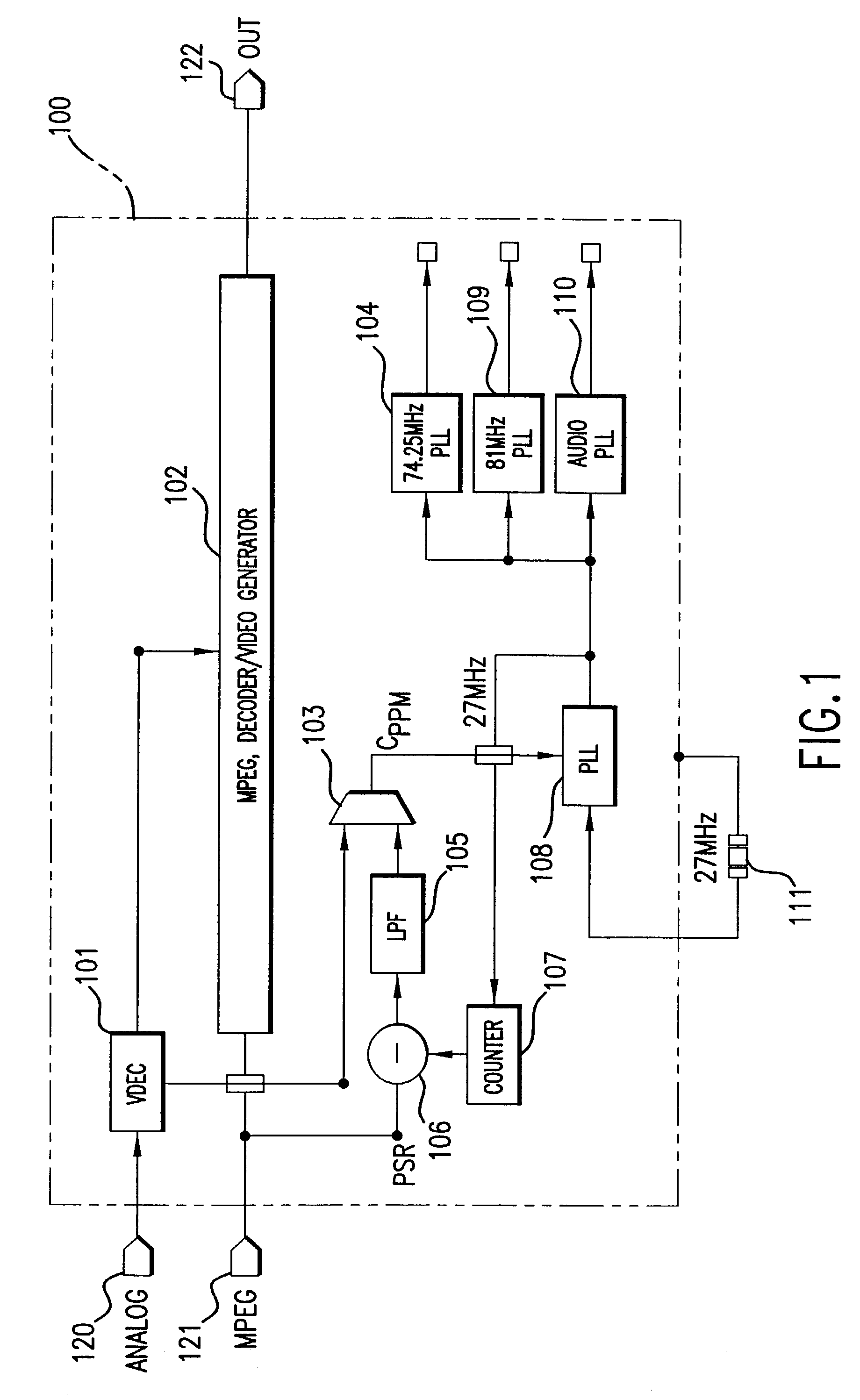
[0035]The present invention relates to systems and methods for generating multiple clock sources from a single reference clock source. The multiple clock sources can be coupled to output circuits that require different frequency clocks.

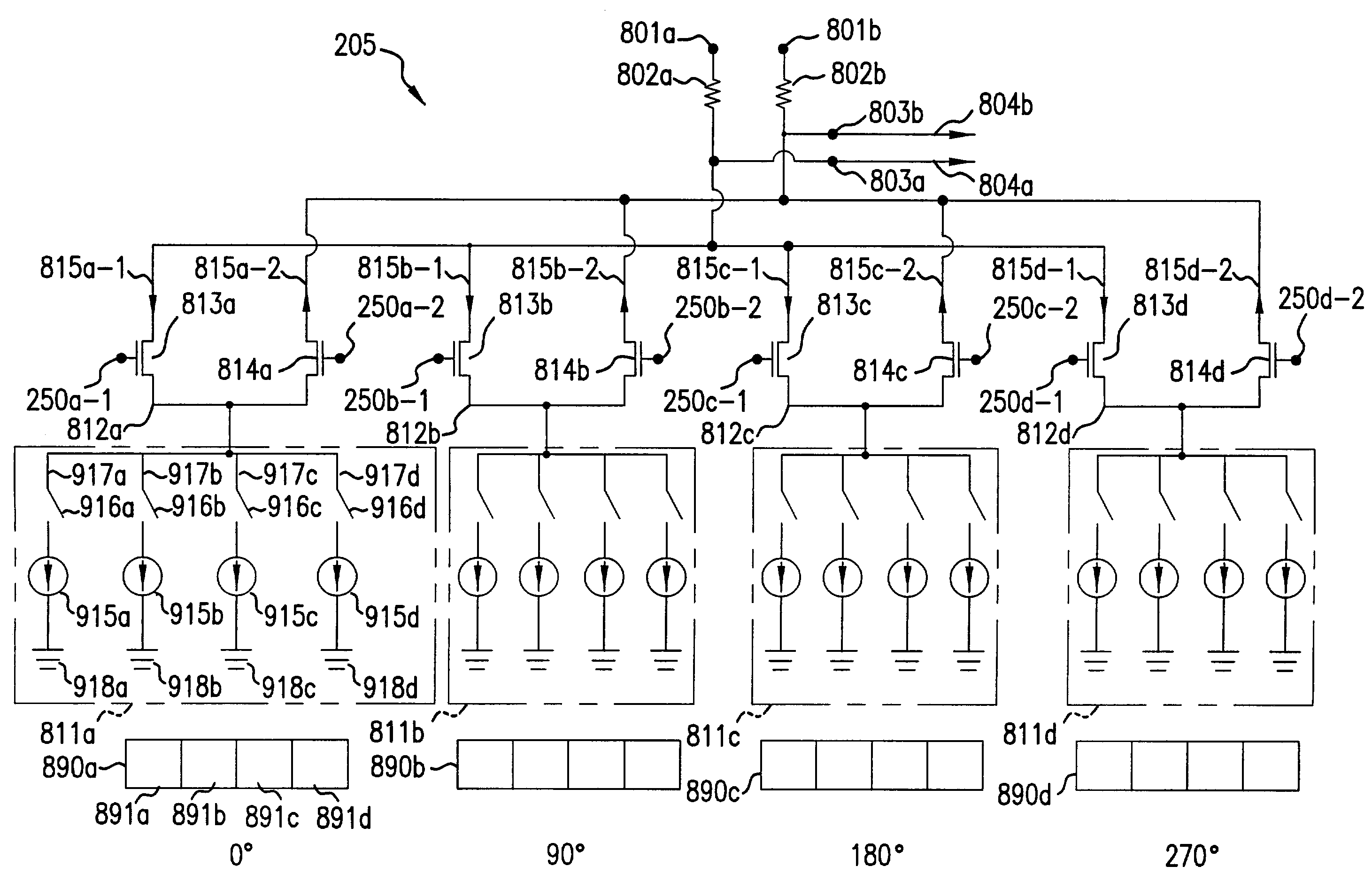
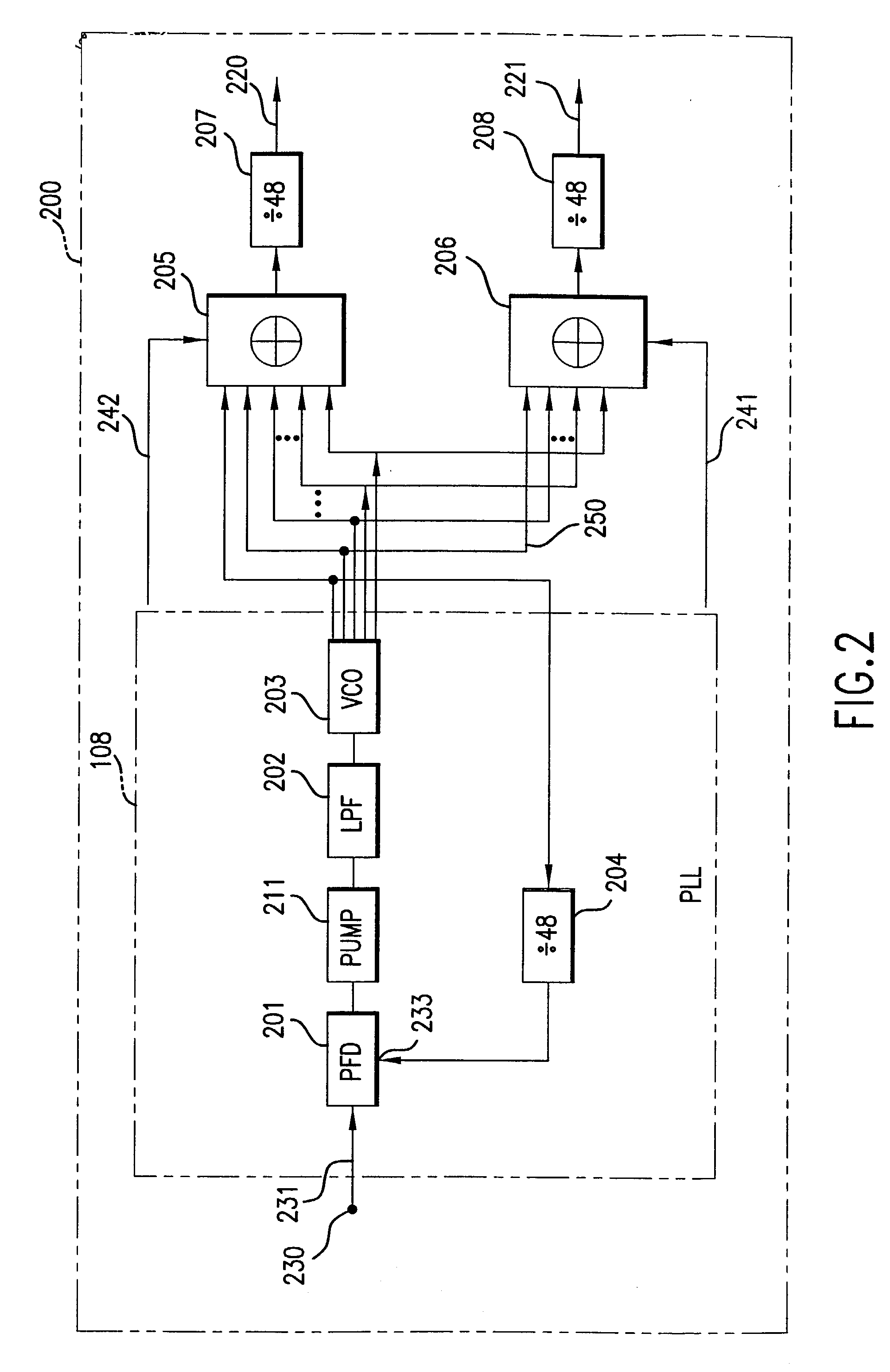
[0036]In an embodiment, the present invention includes plurality of phase rotators coupled to the output of a PLL. The PLL receives a reference signal and generates a plurality of output signals having a respective plurality of phases. The output signals from the PLL are supplied to the plurality of phase rotators. Each phase rotator is configured to (1) assign a relative weighting to the signals from the PLL to form a plurality of weighted signals, and (2) combine the weighted signals to form an output signal,...


PUM


Abstract

A phase rotator generates an output signal having plurality of possible output phases with reduced phase jitter. The low jitter phase rotator includes a plurality of differential amplifiers configured to receive a plurality of input differential signals having different phases, and configured to generate a plurality of weighted signals responsive to the plurality of input differential signals. A plurality of digital-to-analog converters (DAC) are arranged into a plurality of groups, each group of DACs configured to provide current for one of the corresponding differential amplifiers. The number of active DACs in each group of DACs determines a relative weighting of the weighted signals, where relative weighting determining an output phase of an output signal of the phase rotator. The DACs are configured to adjust the output phase of the phase rotator. At a kth phase, N/4 adjacent DACs are activated that are indexed as m0, m1, . . . m((N/4)−1), wherein N is the number of said plurality of DACs. At (k+1)th phase, a m(N/4)DAC is activated that is adjacent to the m((N/4)−1) DAC. At (k+2)th phase, the m0 DAC is de-activated.

Description

RELATED APPLICATIONS[0001]This application claims priority to the U.S. Provisional Application No. 60 / 368,557, filed Apr. 1, 2002, titled “Multiple Synthesized Clocks with Fractional PPM Control from a Single Clock Source”, which is incorporated herein by reference in its entirety.[0002]This application is also related to the following non-provisional application, which is filed on the same date as the present application, and is herein incorporated-by-reference in its entirety: “Multiple Synthesized Clocks with Fractional PPM Control from a Single Clock Source”.BACKGROUND OF THE INVENTION[0003]1. Field of the Invention[0004]The present invention relates to an apparatus for generating multiple clocks from a single reference clock source.[0005]2. Background Art[0006]Electronic systems using MPEG (Moving Pictures Experts Group) compression method for video or audio data is well known. There are several different varieties of MPEG formats currently available. When data is compressed us...

Claims


Application Information

Patent Timeline
IPC IPC(8): H04L7/00G11B20/14H03L7/089H03L7/099H03L7/18
CPCH03L7/0996H03L7/18G11B20/1403H03L7/0891
Inventor CHEN, CHUN YING
Owner AVAGO TECH INT SALES PTE LTD
Why Eureka
Try Eureka