Dynamometric cell

a dynamometric and cell technology, applied in the direction of weighing apparatus, material strength using tensile/compressive forces, electrical/magnetic means, etc., to achieve the effect of adequate signal-to-noise ratio

Inactive Publication Date: 2008-06-03
BAG BIZERBA AUTOMOTIVE GMBH
View PDF30 Cites 4 Cited by
  • Summary
  • Abstract
  • Description
  • Claims
  • Application Information

AI Technical Summary

Benefits of technology

[0011]The dynamometric cell according to the invention thereby combines the advantages of the bolt solutions explained in the above, on the one hand, with the greater accuracy of the solution with the parallelogram guide, on the other hand. In addition, on account of the use of a hollow bar the sensor arrangement can be arranged in the interior thereof and so this can be protected and, in particular, screened from electromagnetic environmental influences. On account of the bar shape of the force transducer, this may easily be designed as a screw bolt which can then take over the same connector function as a substitute for conventional screw bolts but, at the same time, functions in addition as a fully adequate dynamometric cell.
[0044]This ensures that an adequate reserve for the amplification of the effective signal is provided for the evaluation circuit and an adequate signal-to-noise ratio is present.

Problems solved by technology

All the aforementioned dynamometric cells have in common the fact that the force transducer is robust but of a relatively large construction and cannot, therefore, be used for a number of applications where a determination of a weight force would, as such, be desirable.

Method used


Image

  • Dynamometric cell
  • Dynamometric cell
  • Dynamometric cell

Examples


Embodiment Construction

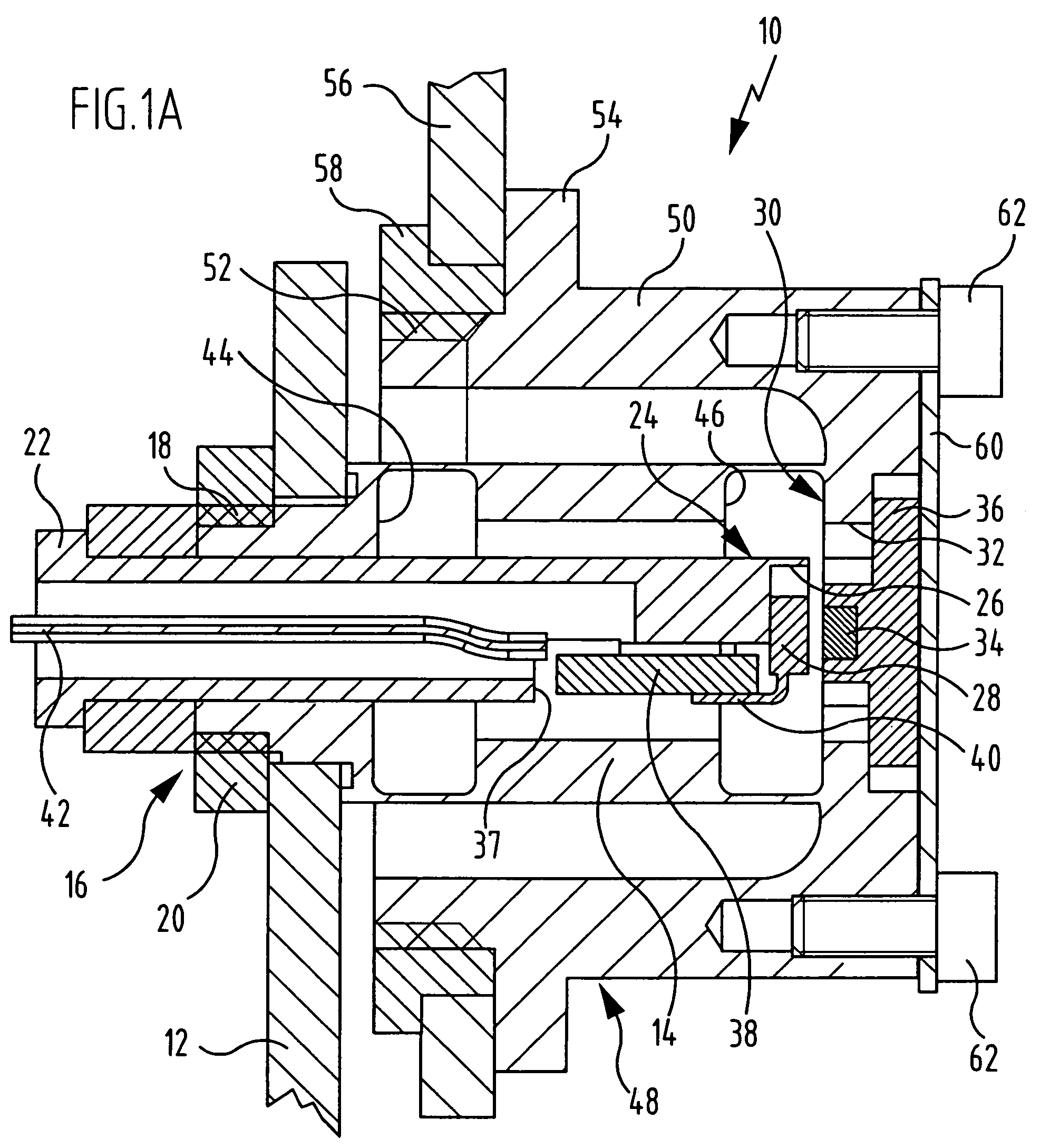
[0062]FIG. 1A shows a dynamometric cell which is given altogether the reference numeral 10 and is held by plate 12 secured to a frame. When the dynamometric cell 10 according to the invention is used in a motor vehicle seat, the plate 12 which is secured to a frame can, for example, be the upper rail of the vehicle seat support.

[0063]The dynamometric cell 10 is constructed from an elastically deformable force transducer 14 which is equipped at a first end located to the left in the drawing with a mounting member 16 which engages through an opening in the plate secured to the frame with a threaded section 18, via which the force transducer 14 can be secured to the plate12 secured to the frame with a counternut 20.

[0064]The force transducer 14 is of a hollow cylindrical design and open on the side of the mounting section 16 so that a flexurally rigid retaining element 22 can be inserted coaxially in the hollow space of the force transducer 14. The retaining element 22 itself is also p...


PUM

PropertyMeasurementUnit
weightaaaaaaaaaa
lengthaaaaaaaaaa
elastic deformationaaaaaaaaaa

Abstract

A dynamometric cell having an elastically deformable force transducer for receiving a weight force and a sensor arrangement for detecting the deformation of the force transducer and its conversion into an electric weight signal is disclosed, wherein the force transducer is connected to a mounting member at its first end and supports a force introduction member at its second end, such that it allows a more exact determination of weight force even when it is incorporated into narrow spaces and wherein the force transducer is designed as a hollow bar with two attenuation zones spaced in longitudinal direction of the bar.

Description

CROSS-REFERENCE TO RELATED APPLICATIONS[0001]This application is a continuation-in-part of International application No. PCT / EP2004 / 002953 filed on Mar. 20, 2004.[0002]The present disclosure relates to the subject matter disclosed in International application No. PCT / EP2004 / 002953 of Mar. 20, 2004 and German application number 103 13 828.5 of Mar. 21, 2003, which are incorporated herein by reference in their entirety and for all purposes.BACKGROUND OF THE INVENTION[0003]The invention relates to a dynamometric cell with an elastically deformable force transducer for receiving a weight force and a sensor arrangement for detecting the deformation of the force transducer and its conversion into an electric weighing signal, wherein the force transducer is connected to a mounting member at a first end and supports a force introduction member at its second end.[0004]Dynamometric cells of this type are used in a variety of ways and are known in different forms.[0005]DE 44 206 91 C1, for exa...

Claims


Application Information

Patent Timeline
Patent Type & Authority Patents(United States)
IPC IPC(8): G01L1/00G01B7/14B60R21/01B60R21/015G01G19/414
CPCB60R21/01516G01G19/4142
Inventor SELIG, KLAUS PETERWURSTER, KLAUS
Owner BAG BIZERBA AUTOMOTIVE GMBH
Why Eureka
Try Eureka