Flexible airbag flap

a flexible and airbag technology, applied in the direction of pedestrian/occupant safety arrangement, vehicle components, vehicular safety arrangments, etc., can solve the problems of more stringent legal requirements and especially time-consuming practice, and achieve the effect of convenient and convenient connection and economic and time-saving production

Active Publication Date: 2008-06-03
LISA DRAXLMAIER GMBH
View PDF21 Cites 31 Cited by
  • Summary
  • Abstract
  • Description
  • Claims
  • Application Information

AI Technical Summary

Benefits of technology

[0008]The flexible airbag flap according to the invention can be produced particularly simply and preferably in a single operation and provides sufficient surface quality and process safety. It has surprisingly been shown that on use of a frame integrated in the decor carrier to attach the airbag module, the wall thickness and hence also the mass of the flexible airbag flap can be reduced to a minimum even when the decor carrier is designed and produced as one piece, while still retaining a sufficient stability of the airbag covering and the required process safety when the airbag is deployed. In addition, the flexible airbag flap according to the invention surprisingly provides the possibility of providing a tolerance compensation of around 2 mm between the decor carrier and the airbag module and hence compensate for production inaccuracies of components to be mounted without disadvantages for the process safety.
[0043]In a further preferred embodiment of the method according to the invention the frame is connected with the decor carrier such that the connecting means of the decor carrier, preferably the threaded bushes, are accessible for subsequent assembly of the airbag module without essential reworking. This allows a particularly economic and time-saving production of an interior trim part with airbag module arranged thereon.

Problems solved by technology

In the past, this problem also led to more stringent legal requirements for a new design of the decor carrier arranged above an airbag.
However, this process proved in practice to be especially time-consuming and caused considerable disadvantages in view of the surface quality of the decor carrier and the processing safety when using the airbag.

Method used


Image

  • Flexible airbag flap
  • Flexible airbag flap
  • Flexible airbag flap

Examples


Embodiment Construction

[0006]The object of the invention is therefore to provide a flexible airbag flap of an airbag module without the problems in the prior art.

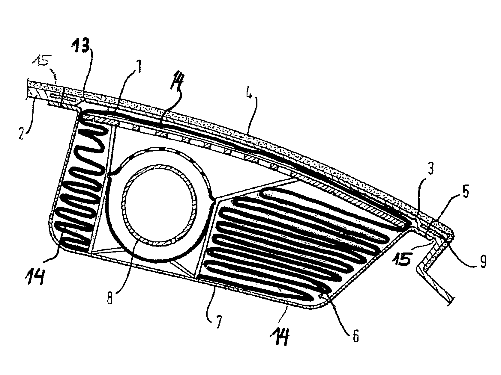
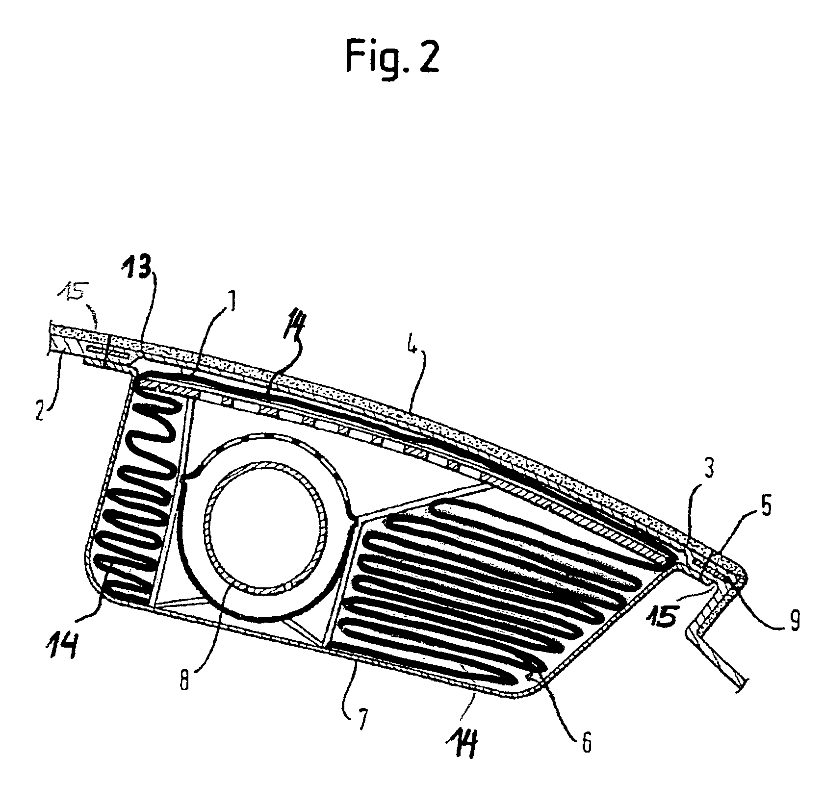
[0007]According to the invention, a frame, preferably a metal frame, is connected with a decor carrier of an instrument panel and the airbag module fastened to this frame. Here there is no need also to attach the airbag module to a cross member supporting the instrument panel. According to the present invention, the decor carrier is produced as one piece and has reduced wall thickness in the area of the flexible airbag flap. The flexible airbag flap is essentially supported by the airbag stored in the airbag module below the decor carrier. In the method of producing such a flexible airbag flap, the frame according to the invention is arranged in a forming tool and then connected to a material, preferably foaming, and forming the decor carrier and the flexible airbag flap.

[0008]The flexible airbag flap according to the invention can be produced pa...


PUM


Abstract

A flexible airbag flap of an airbag module, in particular for use in motor vehicles, where the airbag module is arranged on a frame, preferably a metal frame, connected with a decor carrier of an instrument panel, and attached to the decor carrier but not to a cross member supporting the instrument panel. The flexible airbag flap can essentially be supported by the airbag arranged in the airbag module. The decor carrier is designed as one piece with the flexible airbag flap and in the area of the flexible airbag flap has a reduced wall thickness. Also disclosed is a method for production of such a flexible airbag flap with the steps of arranging the frame and preferably an additional layer covering the frame in a forming tool, and connecting the frame with a material, preferably a foaming material, that forms the decor carrier and the flexible airbag flap.

Description

FIELD OF THE INVENTION[0001]The invention relates to a flexible airbag flap of an airbag module, in particular for use in motor vehicles, and a method for the production thereof.PRIOR ART[0002]For the protection of the passengers in motor vehicles an airbag arranged in an airbag module is usually mounted behind an interior trim panel fitted with a decor layer. In the event of a collision, a shot module also mounted in the airbag module is activated, whereby an airbag usually arranged folded or rolled up is filled explosively with a gas. By the associated volume expansion of the airbag, parts of the interior trim are blasted from their position or at least bent to one side.[0003]Here the interior trim panels are designed such that they break open along previously defined tear lines and thereby allow the unhindered expansion of the airbag to its desired size. In this process, above all it must be ensured that the passengers to be protected by the airbag cannot be hindered or hurt by t...

Claims


Application Information

Patent Timeline
Patent Type & Authority Patents(United States)
IPC IPC(8): B60R21/20B60R21/205B60R21/2165
CPCB60R21/205B60R21/2165
Inventor LANZINGER, MARCUSSACHTLEBEN, BERNDMUELLER, HENRYZIEGLER, HERBERTWINTERHOFF, THOMASSCHLEMMER, CHRISTIAN
Owner LISA DRAXLMAIER GMBH
Why Eureka
Try Eureka