
Technique for reconstructing PET scan images

a scan image and reconstruction technology, applied in the field of medical imaging, can solve the problems of computational demands, inability to accurately measure the energy of each detected photon, and confusion in the data collection and image reconstruction process

Active Publication Date: 2008-06-03
GENERAL ELECTRIC CO
View PDF14 Cites 53 Cited by
  • Summary
  • Abstract
  • Description
  • Claims
  • Application Information

AI Technical Summary

Benefits of technology

This approach reduces computational demands and image noise, providing more accurate and efficient TOF-PET image reconstruction by correcting for scatter and random coincidences in real-time, while minimizing storage requirements.

Problems solved by technology

In addition to the true coincidence events described above, two other types of coincidence events are detected by the PET scanner, and these events confound the data collection and image reconstruction process.
However, due to practical considerations in the design of PET detectors, the energy of each detected photon cannot be measured exactly, and some scattered photons, and therefore some scattered coincidences, are accepted by the scanner.
The techniques range from analytical methods which are computationally efficient to iterative reconstruction techniques which can be computationally demanding.
In addition, considering that image reconstruction will require a sinogram each for prompts, scatter and randoms coincidences, this can result in a significant computational and data storage burden.
On the other hand, the PET sinograms usually are sparsely populated.
However, during image reconstruction, computations are performed on all the sinogram elements, whether zero or non-zero, resulting in a considerable waste of computation resources on empty sinogram bins.
That is, the existing list-mode iterative image reconstruction methods do not guarantee reliable results in situations where the random and scattered coincidences form a substantial fraction of the acquired data set.
Second, since the random coincidences estimate is computed from a noisy acquisition, it can result in increased image noise.

Method used


Image

  • Technique for reconstructing PET scan images
  • Technique for reconstructing PET scan images
  • Technique for reconstructing PET scan images

Examples


Embodiment Construction

[0029]Reference will now be made in detail to exemplary embodiments of the invention, examples of which are illustrated in the accompanying drawings.

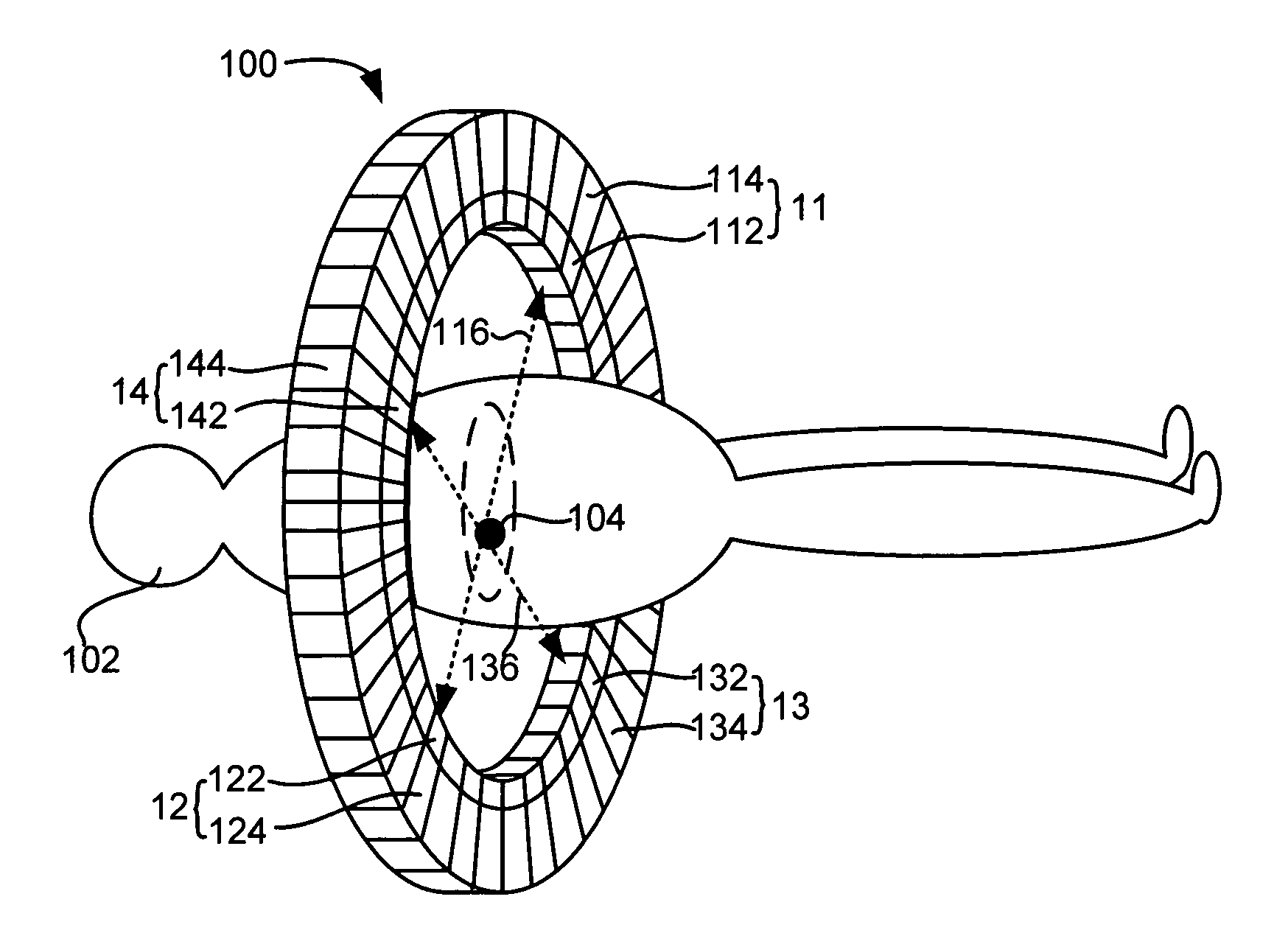
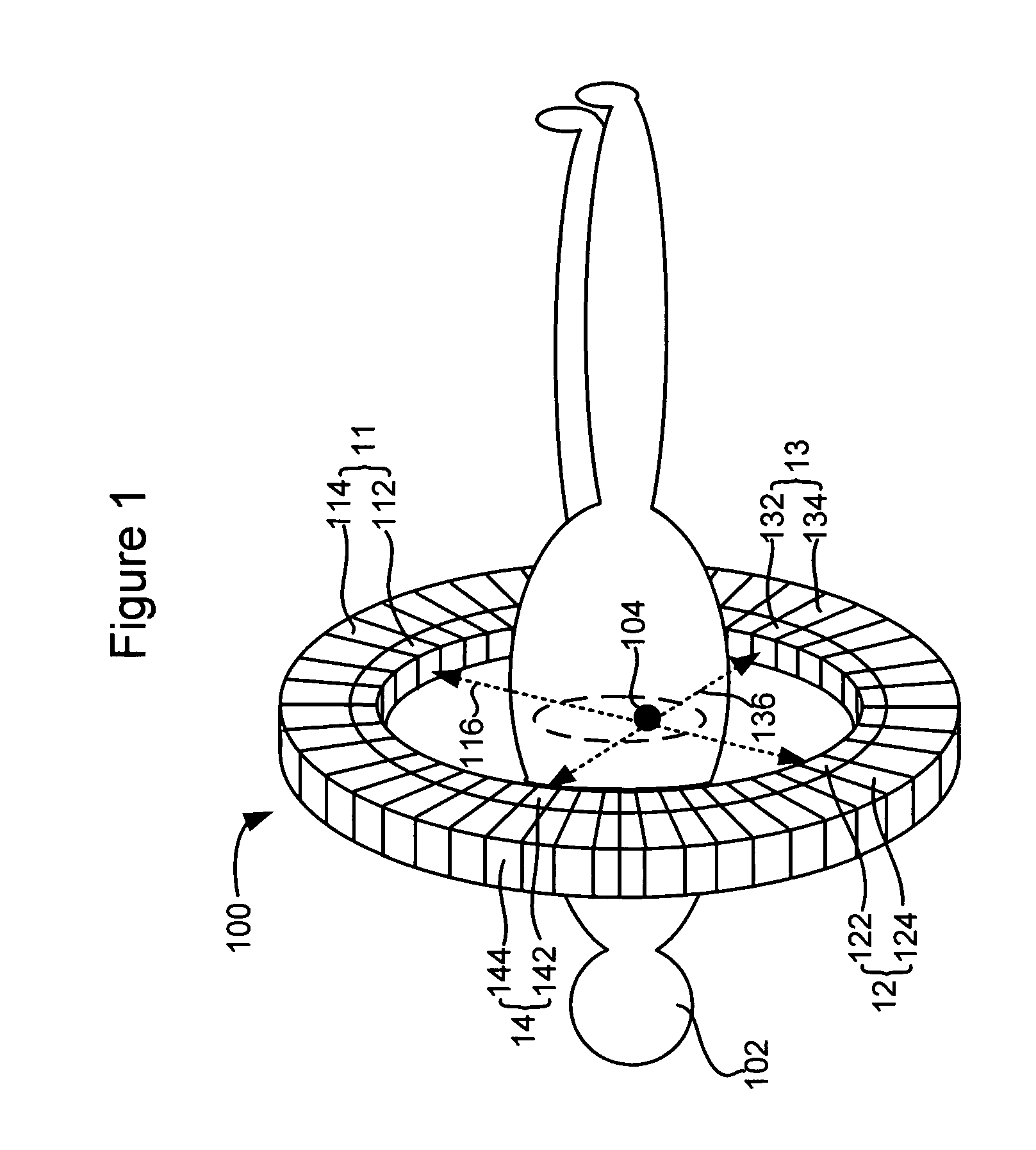
[0030]Embodiments of the present invention may improve TOF PET image reconstruction by collecting detected coincidence events in a list mode and adapting the reconstruction algorithm to the list mode. Instead of being binned into sinograms, the detected events may be stored as a list of coincidence event pairs, along with information about the LORs along which they were detected, the difference in the times stamps of the two photons, and potentially other information like the energy of the individual photons. Embodiments of the improved list-mode TOF PET image reconstruction method may further provide corrections to the list-mode data to minimize interferences from scatter and random events.

[0031]FIG. 4 is a flow chart illustrating an exemplary method for reconstructing PET scan images according to an embodiment of the present invention...


PUM


Abstract

The invention is directed to a technique for reconstructing PET scan images. According to one embodiment, the invention relates to a method for reconstructing PET scan images. The method comprises: detecting a plurality of coincidence events in a PET scanner; storing data associated with the plurality of coincidence events in a chronological list based on a detection time for each of the plurality of coincidence events; generating correction data based on scatter coincidence events and random coincidence events in the plurality of coincidence events; and reconstructing one or more PET scan images based at least in part on the chronological list of data and the correction data.

Description

BACKGROUND OF THE INVENTION[0001]The present invention relates generally to the field of medical imaging and more particularly to a technique for reconstructing PET scan images.[0002]Positron emission tomography (PET) is a technique commonly used in clinical medicine and biomedical research to create images of a living body in its active state. PET scanners can produce images that illustrate various biological process and functions. In a PET scan, the patient is initially injected with a radiotracer. A radiotracer comprises bio-chemical molecules that are tagged with a positron emitting radioisotope and can participate in certain physiological processes in the patient's body. Typical positron-emitting PET isotopes include 11C, 13N, 15O and 18F. When positrons are emitted within the body, they combine with electrons in the neighboring tissues and annihilate. The annihilation events usually result in pairs of gamma photons, with 511 keV of energy each, being released in opposite direc...

Claims


Application Information

Patent Timeline
Patent Type & Authority Patents(United States)
IPC IPC(8): G01T1/163
CPCG01T1/2985
Inventor MANJESHWAR, RAVINDRA MOHANJANSEN, FLORIBERTUS PHILIPPUS MARTINUS HEUKENSFELDTSTEARNS, CHARLES WILLIAM
Owner GENERAL ELECTRIC CO
Learn More