Supercharge Your Innovation With Domain-Expert AI Agents!

Illumination apparatus, in particular slit lamp

a technology of illumination apparatus and slit lamp, which is applied in the field of illumination apparatus, can solve the problems of insufficient attempts to solve the problem, insufficient attempts to eliminate the drawbacks arising therefrom, and the loss of considerable portions of usable light from the light guide or any other light-emitting means

Inactive Publication Date: 2008-06-03
LEICA INSTR SINGAPORE PTE
View PDF7 Cites 3 Cited by
  • Summary
  • Abstract
  • Description
  • Claims
  • Application Information

AI Technical Summary

Benefits of technology

This solution achieves maximum light utilization and prevents absorption, providing a more efficient and homogeneous illumination with improved contrast and adaptability for diagnostic and surgical procedures, allowing for precise control of the illumination beam's shape and direction.

Problems solved by technology

A substantially larger portion of the light, however, is absorbed on the mechanical slit aperture and converted into heat, and thus does not contribute to the intensive illumination of the slit image onto the patient's eye.
This conventional embodiment thus creates the problem that because of the transition from the circular surface (exit surface of the light guide) to the rectangular surface (entrance surface of the slit aperture), considerable portions of the usable light from the light guide or from any other light-emitting means are lost.
This problem is not unknown, but the attempts to solve it, in order to eliminate the drawbacks arising therefrom, are insufficient.
On the one hand, however, this action does not appreciably prevent the light loss, and on the other hand a cylindrical lens makes the light distribution in the slit inhomogeneous.

Method used


Image

  • Illumination apparatus, in particular slit lamp
  • Illumination apparatus, in particular slit lamp
  • Illumination apparatus, in particular slit lamp

Examples


Embodiment Construction

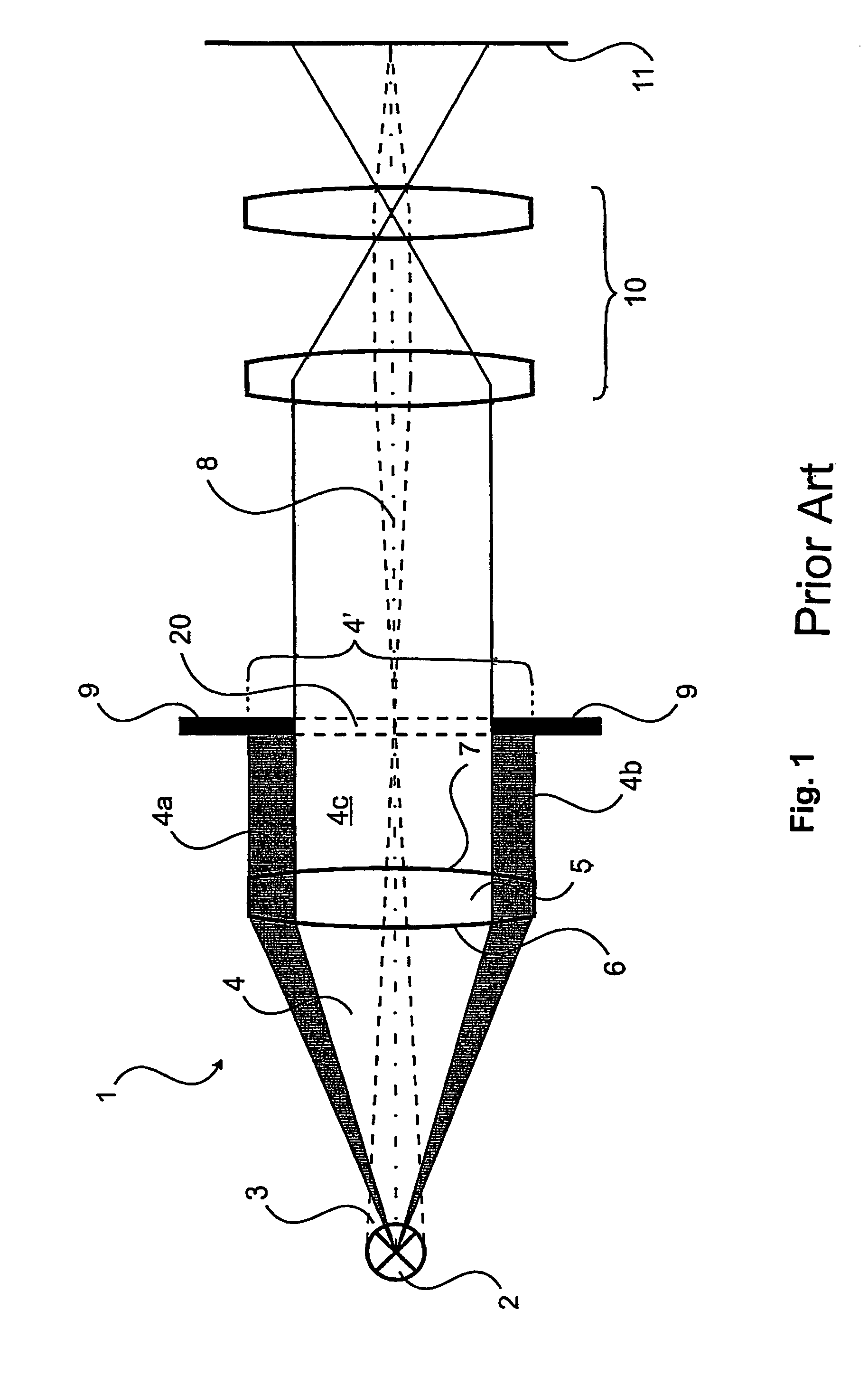
[0044]FIG. 1 is a longitudinally sectioned depiction of an illumination apparatus 1 that is used according to the existing art as a slit lamp. Here a light-emitting means 2 generates an image beam 3 and an illumination beam 4 which proceed along an optical axis 8. These two beam strike an optical element 5 (usually a converging lens) that has a light entrance surface 6 and a light exit surface 7. Optical element 5 bundles illumination beam 4 onto a slit aperture 9 that has a slit-shaped opening 20. As a result, only the light bundle of illumination beam 4 corresponding to slit aperture opening 20 can now pass through slit aperture 9. Resultant illumination beam 4′ is thus made up of an actually utilized portion 4c of illumination beam 4, and two (in this sectioned depiction) unutilized portions 4a and 4b that are absorbed by slit aperture 9 and converted into heat. The slit-shaped light beam that thus remains is then imaged by an imaging optic 10 onto illuminated plane 11, which as ...


PUM


Abstract

An illumination apparatus, usable for example as a slit lamp, comprises a light-emitter (2) and an optical element (12) having a free-form surface (13), and optionally a slit aperture (9) and an imaging optic (10). The concept of the present invention is that the free-form surface (13) is employed to generate a resultant illumination beam having a slit-shaped cross-section.

Description

CROSS REFERENCE TO RELATED APPLICATIONS[0001]This application claims priority of the German patent application 10 2004 028 471.7 filed Jun. 11, 2004 which is incorporated by reference herein.FIELD OF THE INVENTION[0002]The invention concerns an illumination apparatus, in particular a slit lamp, that is used for surgery and the diagnosis of certain eye diseases.BACKGROUND OF THE INVENTION[0003]A “slit lamp” is understood to be a device that is used to observe the front portion of the eye (lens and proximal vitreous body), and to monitor contact lens fittings. The slit image facilitates diagnostic and surgical procedures. During operations, it is used as a contrast-enhancing illumination in the region of the retina.[0004]Slit lamps of this kind are very well known, and are manufactured by several suppliers and used routinely by doctors.[0005]The existing art includes slit lamps in which a slit aperture is illuminated, directly or via a light guide, by means of a light-emitting means. ...

Claims


Application Information

Patent Timeline
Patent Type & Authority Patents(United States)
IPC IPC(8): G02B21/06A61B3/10F21S2/00A61B3/12A61B3/135A61F9/007F21W131/20F21Y101/00G01T1/166G02B21/00G02B27/09
CPCA61B3/135G02B27/095
Inventor SANDER, ULRICH
Owner LEICA INSTR SINGAPORE PTE
Features
  • R&D
  • Intellectual Property
  • Life Sciences
  • Materials
  • Tech Scout
  • Unparalleled Data Quality
  • Higher Quality Content
  • 60% Fewer Hallucinations
Learn More