Method and device for reducing high frequency error components of a multi-channel modulator

a multi-channel modulator and high frequency error technology, applied in the field of multi-channel audio amplifiers, can solve the problem of substantially the same errors in the output of the channels of the modulator

Inactive Publication Date: 2008-06-03
NOKIA CORP
View PDF9 Cites 11 Cited by
  • Summary
  • Abstract
  • Description
  • Claims
  • Application Information

AI Technical Summary

Benefits of technology

[0037]The major advantage of the present invention is that bulky, fragile and expensive

Problems solved by technology

If e.g. substantially similar signals are modulated with e.g. the same modulation signal,

Method used


Image

  • Method and device for reducing high frequency error components of a multi-channel modulator
  • Method and device for reducing high frequency error components of a multi-channel modulator
  • Method and device for reducing high frequency error components of a multi-channel modulator

Examples


Embodiment Construction

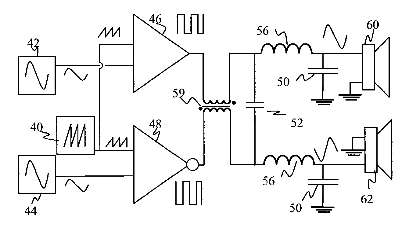
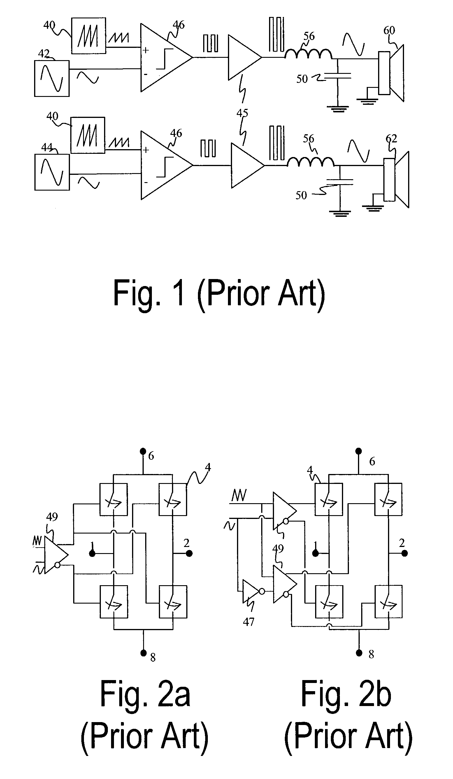
[0045]FIG. 1 is a block diagram of a conventional two-channel pulse width modulation amplifier (PMA), embodied as two parallel one-channel amplifiers. The single channels have two different input terminals or signal sources 42 and 44, for the input of signals to be amplified. The signal to be amplified is e.g. an analogue signal as indicated by the sine wave in the signal sources 42,44. The signal to be amplified is fed to comparators 46, to be compared with a comparison waveform. The comparison waveform is fed from one or more comparison waveform generators (CWG) 40. The comparison waveform is a triangular or saw-tooth shaped signal, as indicated by the saw-tooth in the comparison waveform generators 40. The use of one or more CWGs 40, may depend on the actually used components or the actually used circuit board design. Conventional PMAs using only one CWG 40, do this only for the sake of simplicity and expense, not for the sake of electro-magnetic compatibility (EMG). The comparat...


PUM


Abstract

A method and device for reducing error components of a multi-channel modulator. The method comprises the steps of inverting substantially half of the channels of a modulator, and reducing error components between said inverted channels and said non inverted channels by inductive and/or capacitive summing. The method is especially suitable for synchronized pulses and similar signals to be modulated.

Description

CROSS-REFERENCE TO RELATED APPLICATIONS[0001]This application claims priority under 35 USC §119 to International Patent Application No. PCT / IB02 / 01379, having an international filing date of Apr. 25, 2002.TECHNICAL FIELD[0002]The present invention relates to multi-channel audio amplifiers and more particular to noise reduction of those with a minimized use of large filters and coils.BACKGROUND OF THE INVENTION[0003]Pulse modulated audio amplifiers are based on a switching principle which minimizes the power losses. The output transistor is only on or off—and does not work resistively like in traditional class amplifiers. Such switching causes high frequency energy and electromagnetic compatibility (EMC) problems to the output signals. There is high frequency energy because of a modulated square wave with a high carrier frequency. The high frequency energy is primarily in the carrier frequency and its harmonics.[0004]Low pass filtering can be used to prevent unwanted energy going int...

Claims


Application Information

Patent Timeline
IPC IPC(8): H04B15/00H03C1/02H03F1/04H03F1/26H03F1/30H03F1/34H03F3/217H04R5/04
CPCH04R5/04
Inventor BRODKIN, PANU
Owner NOKIA CORP
Why Eureka
Try Eureka