
Electro-optical module comprising flexible connection cable and method of making the same

a technology of flexible connection cable and electro-optical module, which is applied in the direction of dielectric characteristics, orthogonal pcbs mounting, instruments, etc., to achieve the effect of high integration and high integration of electro-optical modul

Active Publication Date: 2008-06-03
INT BUSINESS MASCH CORP
View PDF16 Cites 29 Cited by
  • Summary
  • Abstract
  • Description
  • Claims
  • Application Information

AI Technical Summary

Problems solved by technology

The reliable, accurate and cost-effective integration of optical elements such as waveguides, transmitters and detectors in PCB's is a challenge lying mainly in high integration and optical alignment.
Consequently, it is a challenge to align optical elements in a printed circuit board.

Method used


Image

  • Electro-optical module comprising flexible connection cable and method of making the same
  • Electro-optical module comprising flexible connection cable and method of making the same
  • Electro-optical module comprising flexible connection cable and method of making the same

Examples


Embodiment Construction

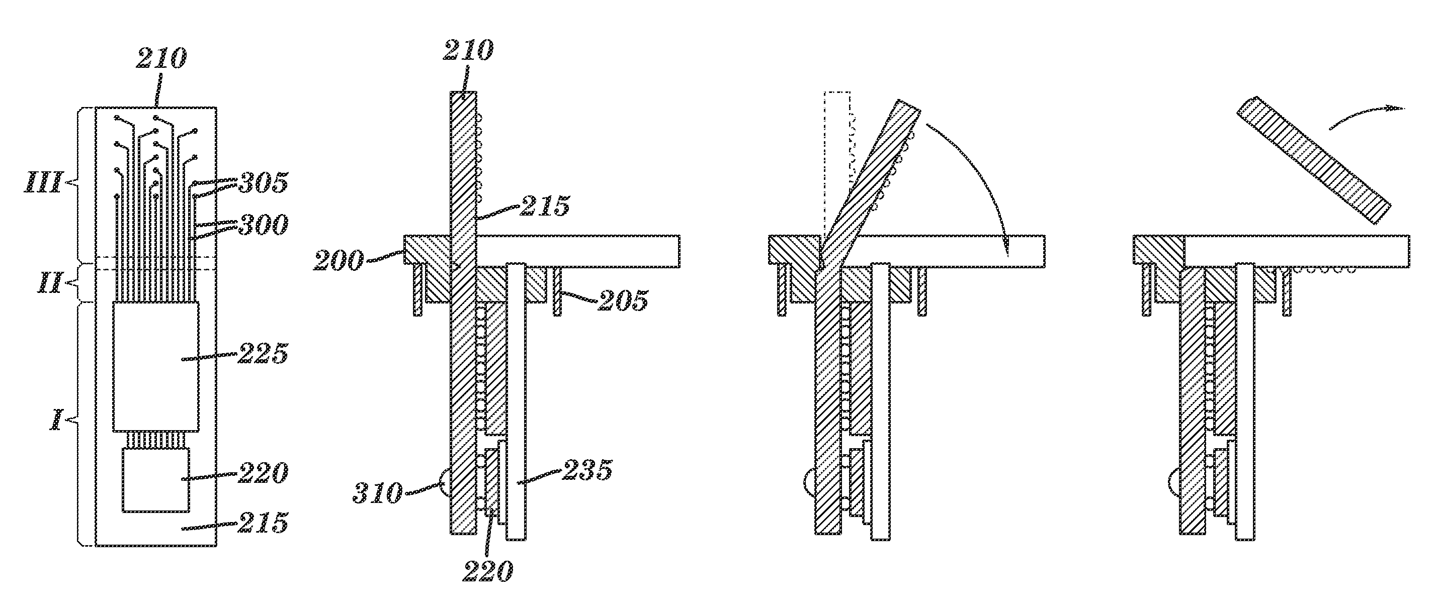
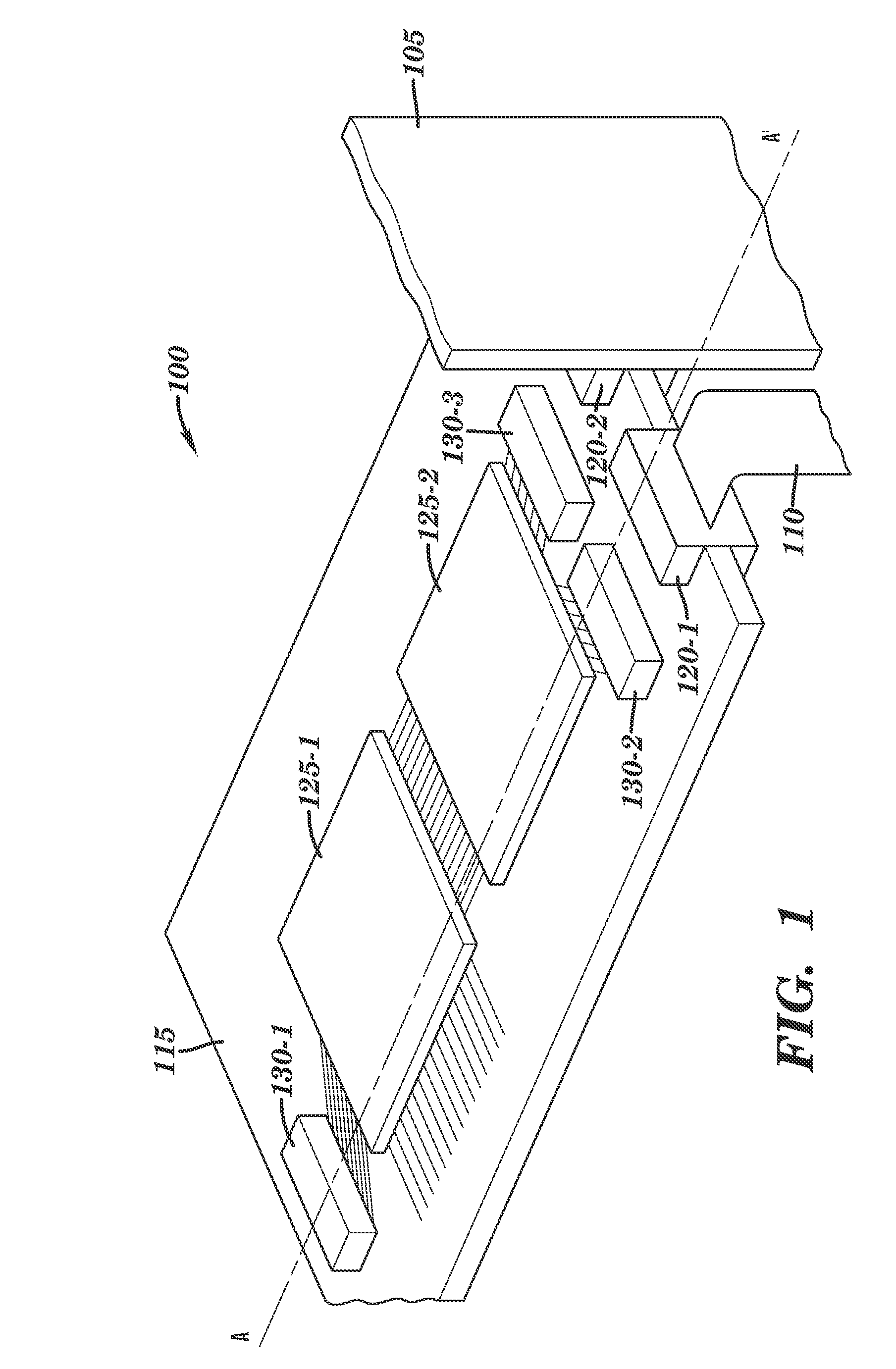
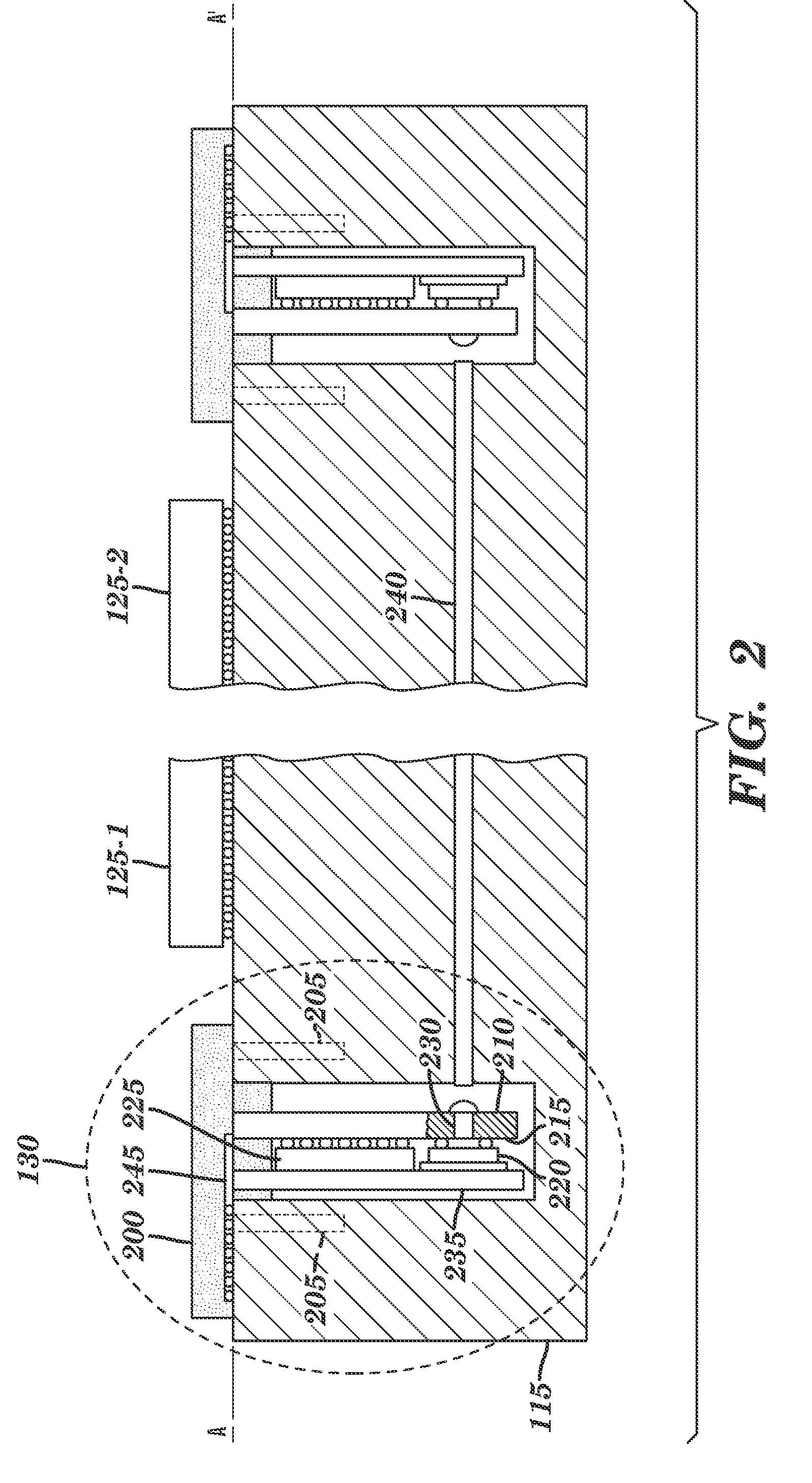
[0026]The present invention introduces a design technique to be used in manufacturing a highly integrated electro-optical module with very small dimensions. According to the invention there is provided means for manufacturing, aligning, and connecting such modules. The number of precise alignment steps, where optics is engaged with the board, is reduced to an absolute minimum, one.

[0027]For sake of illustration the description is based upon Vertical Cavity Surface-Emitting Laser (VCSEL) as well as the associated optical signal detector that need to be assembled into small cavities like the one that can be created into optical back-planes or can be used to connect electrical signals to Micro ElectroMechanical Systems (MEMS) or Micro Opto-ElectroMechanical Systems (MOEMS).

[0028]These modules are designed to allow assembling of one or more devices onto a thermally stable structure with high performance electrical properties. The mounting operations are performed on flat surfaces to mak...


PUM


Abstract

An electro-optical module comprising flexible connection cable and aligning capabilities is disclosed. Electro-optical devices may be soldered on a transparent substrate such as glass or a substrate comprising an optical waveguide wherein electrically conductive traces are designed, forming an electro-optical module. When such electro-optical module is inserted and aligned into a printed circuit board, the external part of the substrate, comprising electrically conductive traces and pads, referred to as flex-cable, is bent down toward the mounting plane of the PCB allowing to establish electrical connections between these pads and the PCB. The substrate may be broken along a pre-formed groove, and the external part of the substrate can be removed leaving the flex-cable section in place.

Description

CROSS-REFERENCE TO RELATED APPLICATIONS[0001]The present application is a divisional of U.S. patent application Ser. No. 10 / 904,271, filed Nov. 2, 2004, hereby incorporated herein by reference.FIELD OF THE INVENTION[0002]The present invention relates generally to optical communication apparatus and more specifically to the implementation of optical interconnect links in printed circuit boards.BACKGROUND OF THE INVENTION[0003]Typically systems that might potentially use optical interconnects within the next few years are servers, supercomputers and telecom switch-routers, comprising multiple racks, wherein each rack has a backplane or midplane, and multiple plug-in cards (or blades). Communication between the plug-in-cards is routed through the backplane. The aggregate data rate within a single rack is expected to reach multiple Terabit per second (Tb / s) by the end of the decade, and it is assumed that it will grow to tens of Tb / s in the future. Currently communication is achieved el...

Claims


Application Information

Patent Timeline
Patent Type & Authority Patents(United States)
IPC IPC(8): G02B6/12
CPCG02B6/43H05K1/0274H05K1/147H05K1/141H05K3/0061H05K3/0067H05K2201/0108H05K2201/044H05K2201/048H05K2201/09127H05K2201/2009
Inventor OGGIONI, STEFANO S.OFFREIN, BERT J.
Owner INT BUSINESS MASCH CORP
Learn More