Method and apparatus for steering a farm implement to a path

a technology of implements and paths, applied in the direction of process and machine control, distance measurement, instruments, etc., can solve the problems of large delay in bringing the implement back on-line, oversteering the tractor, and less accurate positioning of the implements, and achieve the effect of rapid ra

Active Publication Date: 2008-06-03
TRIMBLE NAVIGATION LTD
View PDF24 Cites 64 Cited by
  • Summary
  • Abstract
  • Description
  • Claims
  • Application Information

AI Technical Summary

Benefits of technology

[0013]In prior art, when the implement is directly and firmly attached to the tractor with a three-point hitch, the tractor has to be steered and moved so the implement is then dragged to the proper line, often resulting in a large delay in bringing the implement back on-line with the possibility of oversteering of the tractor and less accurate positioning of the implement. With the present invention, as a tractor is driving along pushing or towing an implement, and an off-line position error is detected, the implement can be quickly be brought on-line by moving the hitch with respect to the tractor.
[0015]The embodiments of the present invention have several advantages over the existing art for guiding a farm implement along a path. In the present invention existing rows are not needed because GPS is used to determine geographical locations, a position correction between the powered vehicle and the farm implement is not needed because the GPS signals are received directly on the farm implement, it is not necessary to add or interface an autopilot for an existing powered vehicle, and the farm implement can be propelled along a precise path at a relatively rapid rate without a requirement for fast steering of the powered vehicle.

Problems solved by technology

In prior art, when the implement is directly and firmly attached to the tractor with a three-point hitch, the tractor has to be steered and moved so the implement is then dragged to the proper line, often resulting in a large delay in bringing the implement back on-line with the possibility of oversteering of the tractor and less accurate positioning of the implement.

Method used


Image

  • Method and apparatus for steering a farm implement to a path
  • Method and apparatus for steering a farm implement to a path
  • Method and apparatus for steering a farm implement to a path

Examples


Embodiment Construction

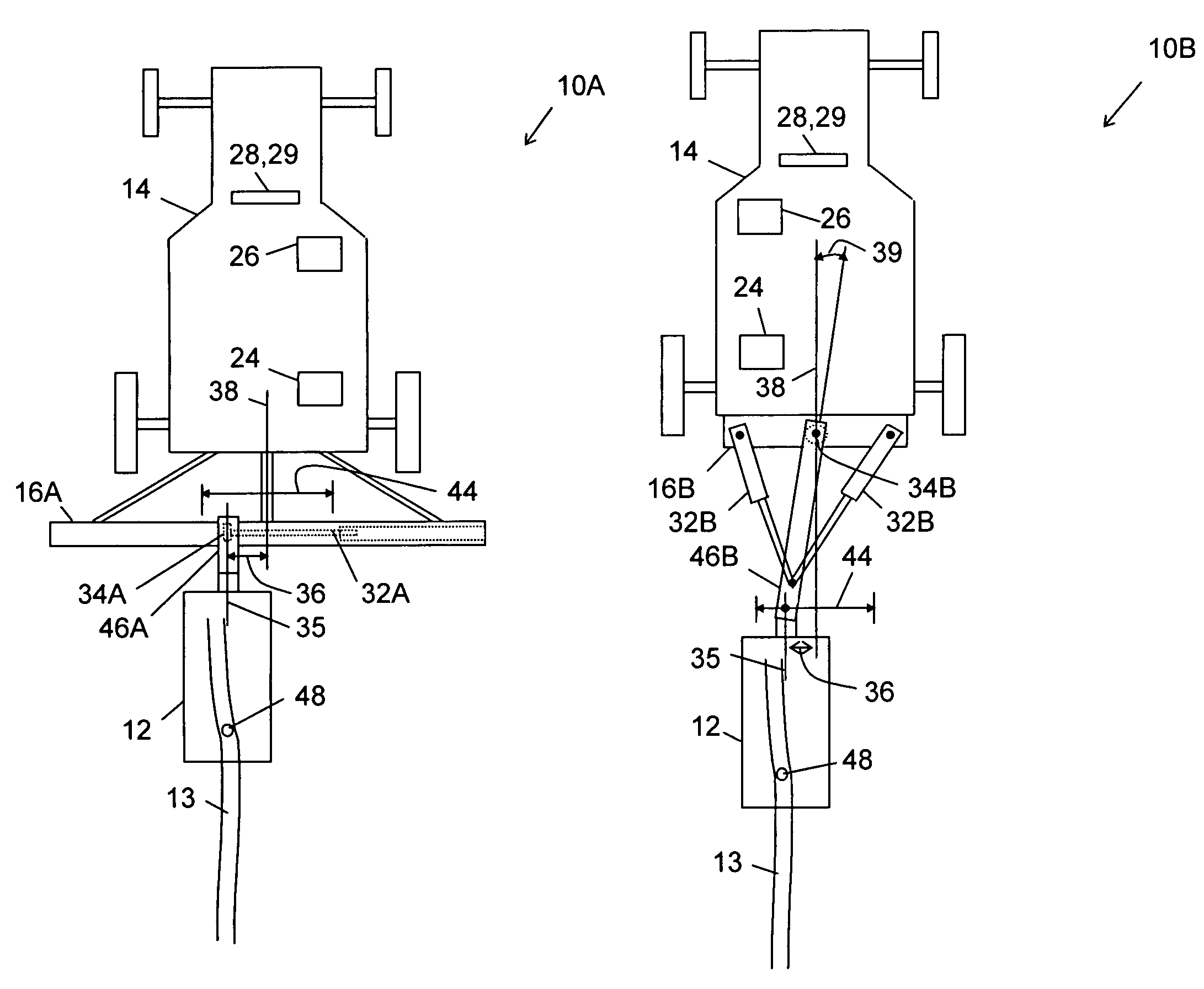
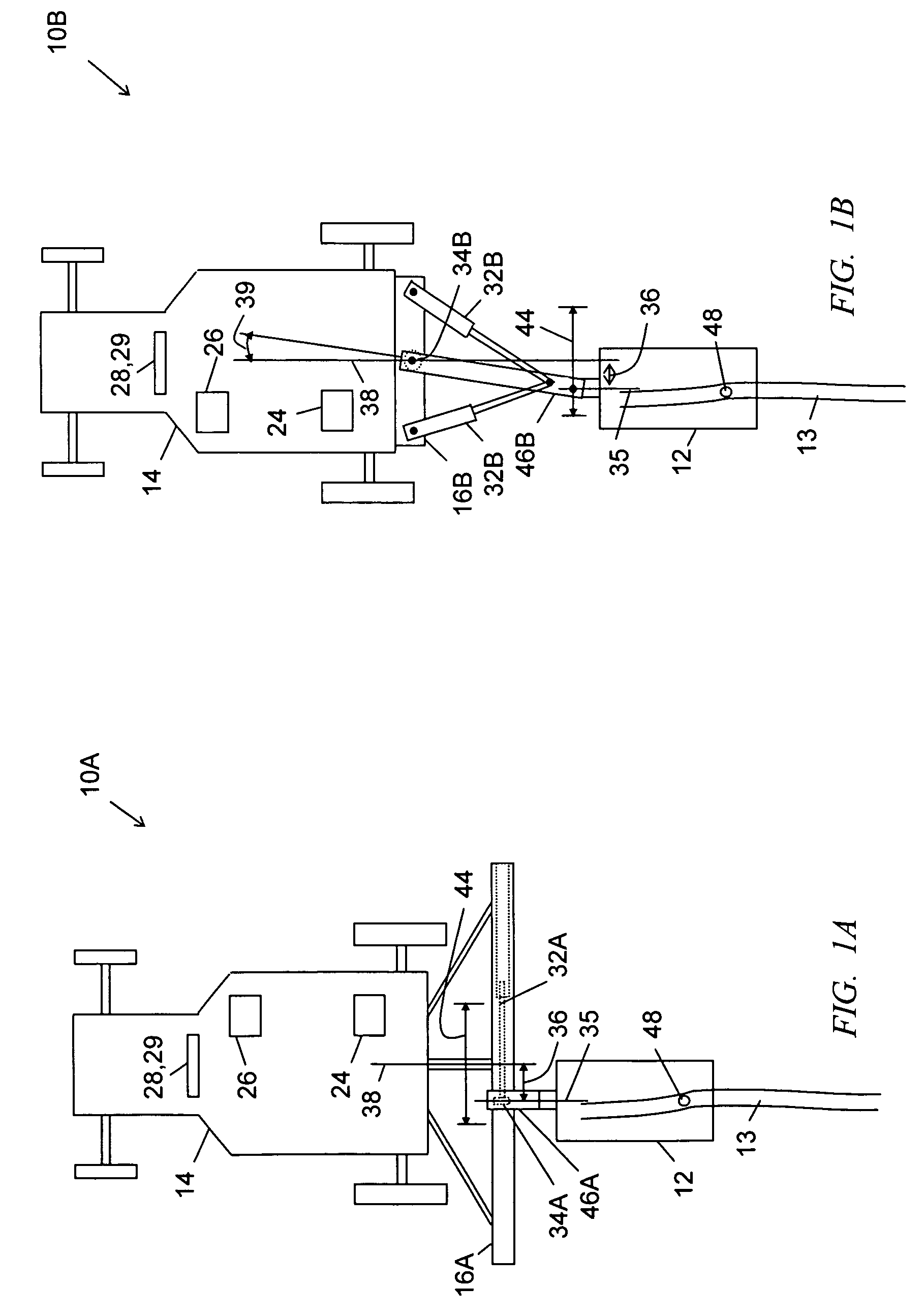
[0023]FIGS. 1A and 1B illustrate embodiments of a farming system of the present invention referred to with reference numbers 10A and 10B, respectively. It is an object of the system 10A,B to guide a farm implement 12 along a path 13 by dynamically adjusting the lateral or left-right position of the implement 12 with respect to a powered vehicle 14 that propels (tows, pulls, or side carries) the implement 12. The implement 12 can be a cultivator, planter, seeder, ripper, or the like.

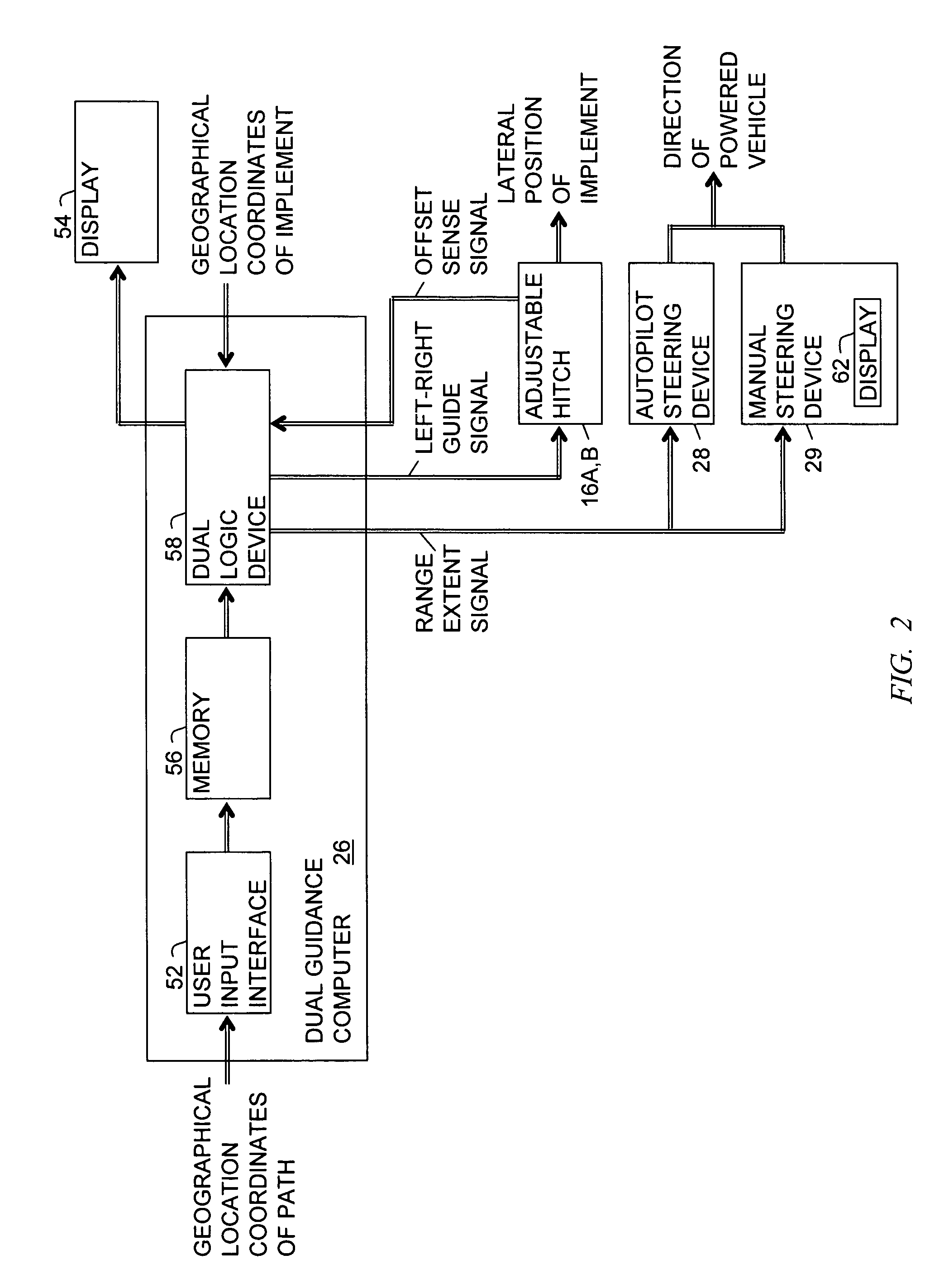
[0024]Referring to FIG. 1A, the system 10A includes the farm implement 12, the powered vehicle 14, an adjustable hitch 16A, a global positioning system (GPS) receiver 24, a dual guidance computer 26, and a vehicle pilot device 28 or 29. The hitch 16A physically connects the implement 12 to the vehicle 14.

[0025]The hitch 16A includes an actuator 32A and a sensor 34A. The implement 12 has a center line 35. The actuator 32A physically positions the implement center line 35 to an adjustable left-right positio...


PUM


Abstract

An apparatus and method using GPS for dynamically adjusting side-to-side positioning of a farm implement along a geographical path. The apparatus includes a global positioning system (GPS) antenna disposed on the farm implement, a GPS receiver coupled to the GPS antenna for determining a location of the GPS antenna, and a dual guidance computer for comparing the location to stored geographical coordinates of a desired path for providing a guide signal for offsetting the lateral position of an adjustable hitch or angling a wheel or ground rudder in a steerable implement for guiding the implement along the path; and a range extent signal for maintaining the offset of the hitch or steering angle of the implement within its dynamic range.

Description

CROSS REFERENCE TO RELATED APPLICATION[0001]This application is a continuation of an application Ser. No. 10 / 652,454 filed Aug. 29, 2003 now U.S. Pat. No. 7,054,731 by the same inventors for the same assignee.BACKGROUND OF THE INVENTION[0002]1. Field of the Invention[0003]The invention relates generally to systems for guiding farm implements and more particularly to an apparatus and method using global positioning system (GPS) locations for dynamically adjusting a farm implement side-to-side to match a predetermined geographical path.[0004]2. Description of the Prior Art[0005]Several companies have developed farm guidance systems for close cultivation of crops. These systems are used to reduce the amount of herbicide that is needed to keep weeds out of the growing area. One such system uses a special form of three-point hitch that is allowed to move side-to-side to track drag wires or guide wheels which follow a row of plants. However, a limitation of the wire and wheel systems occu...

Claims


Application Information

Patent Timeline
Patent Type & Authority Patents(United States)
IPC IPC(8): A01B35/32G05D1/00G06F19/00
CPCA01B69/008
Inventor LANGE, ARTHUR F.FUNK, TIMOTHY J.
Owner TRIMBLE NAVIGATION LTD
Why Eureka
Try Eureka