
Power management apparatus, printer, file server, printing system and computer software

a technology of power management apparatus and printer, which is applied in the direction of instruments, liquid/fluent solid measurement, sustainable buildings, etc., can solve the problems of energy waste, inability to accommodate, energy waste, etc., and achieve the effect of improving usability and saving energy

Active Publication Date: 2008-06-03
SHARP KK
View PDF10 Cites 20 Cited by
  • Summary
  • Abstract
  • Description
  • Claims
  • Application Information

AI Technical Summary

Benefits of technology

The present invention provides a power management apparatus, a printer, and a printing system that can save energy and improve usability by automatically managing the power supply of printers connected to multiple hosts over a network. The apparatus or printer determines the priority of each printer based on the priority of each host and the operation state of the host. The apparatus or printer can also be controlled remotely, based on the priority of each printer. This system can save users from labor and save energy in the entire network without the need for a power management server.

Problems solved by technology

In reality, however, energy is wasted to turn off all the printers shared on a network only after termination of operation of all computers.
Furthermore, in the latter disclosure in which printers to be left turned on are determined on the basis of the priority or frequency of use of the printers, the setting values are averages determined from day-to-day usage and therefore cannot accommodate variations in usage at different times.
Also, the technology disclosed in Japanese Patent Laid-Open No. 2000-172474 causes energy waste because all printers are left turned on until the termination of operation of the last host is recognized.
Therefore, although previous usage of the printers can be reflected in their setting, the setting is not always best suited to possible usage at any given time.

Method used


Image

  • Power management apparatus, printer, file server, printing system and computer software
  • Power management apparatus, printer, file server, printing system and computer software
  • Power management apparatus, printer, file server, printing system and computer software

Examples


first embodiment

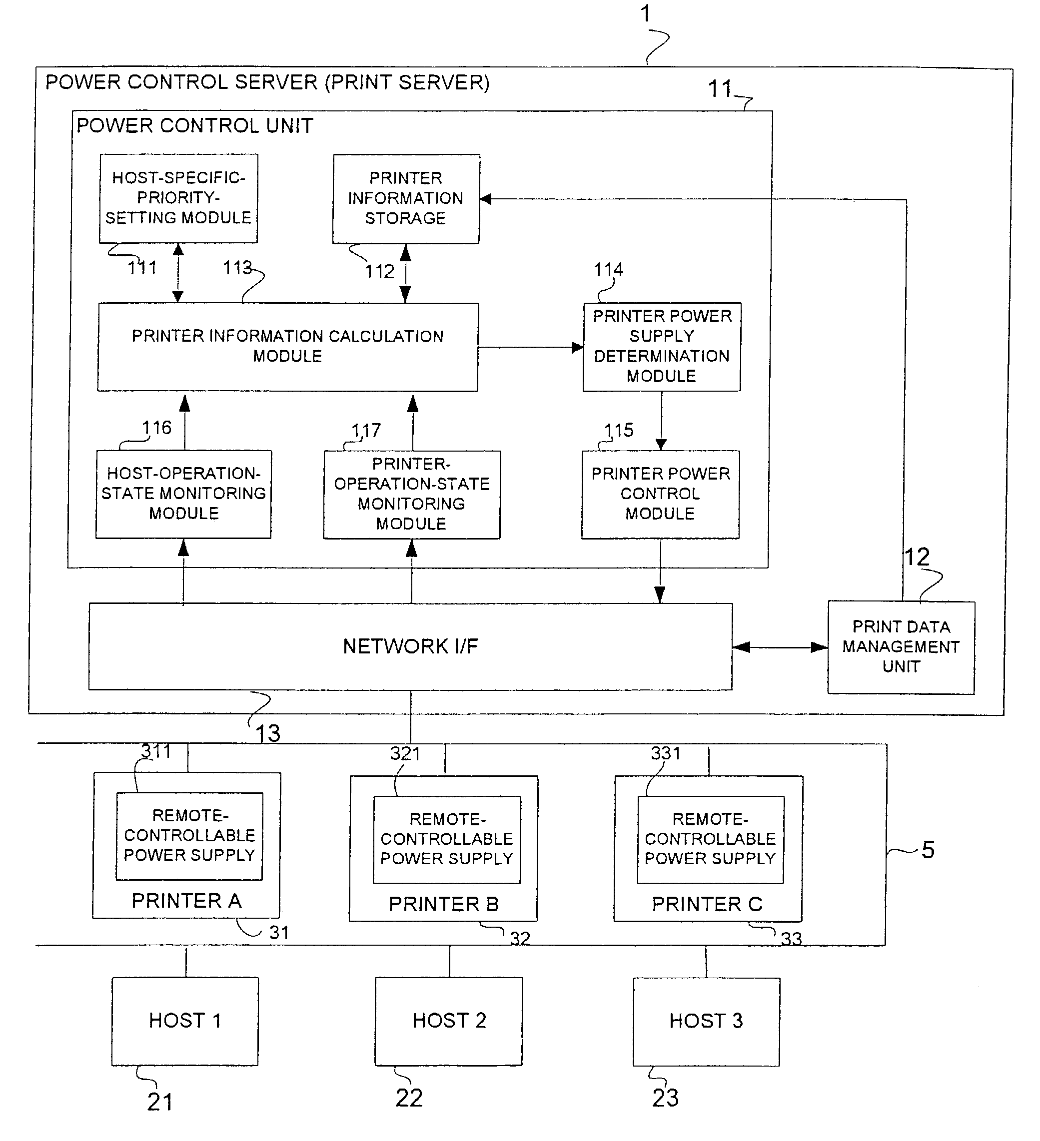
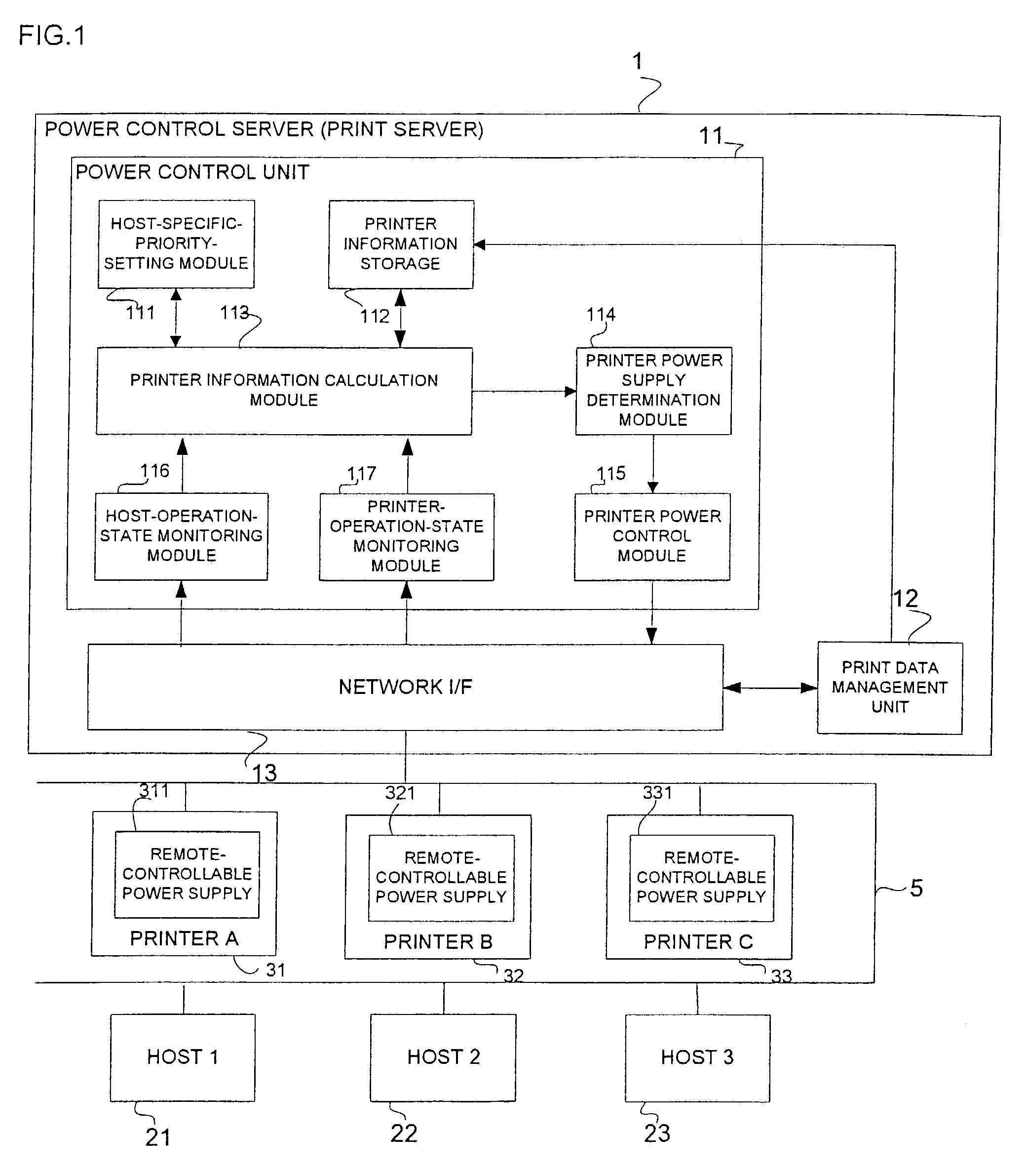
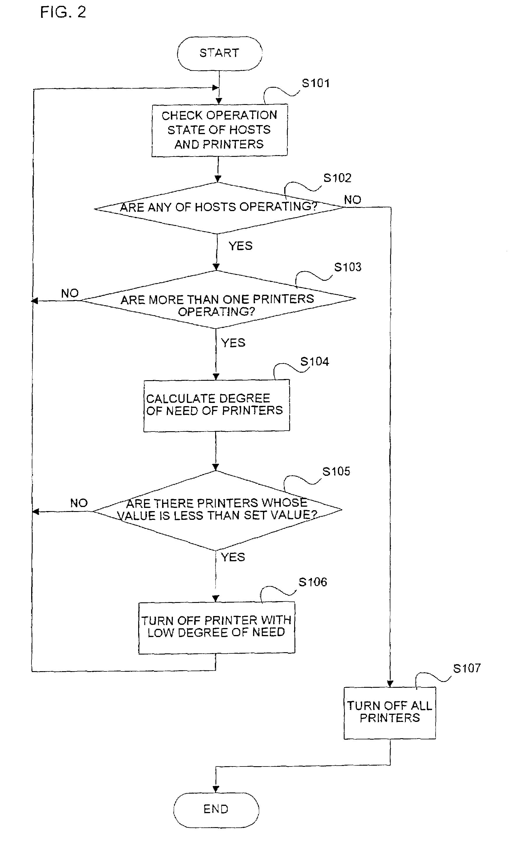
[0088]An example of a power management process performed in the power management apparatus in the printing system according to the present invention will be described with reference to FIG. 2. The power management server 1 monitors through a host-operation-state monitoring module 116 and a printer-operation-state monitoring module 117 the power-on / off sate of the hosts 21 to 23 and the printers 31 to 33 on the network 5 at step S101 to whether any of the hosts are operating at step S102.

[0089]If none of the hosts are operating, then the printer power control module 115 turns off all the printers 31 to 33 at step S107 and the process will end.

[0090]On the other hand, if any of the hosts are operating, the printer-operation-state monitoring module 117 determines at step S103 whether more than one printer is operating.

[0091]If only one of the printers is operating, the printer should be left turned on until all the hosts 21 to 23 are turned off. Therefore, the process returns to step S...

second embodiment

[0121]the present invention will be described below. FIG. 4 shows a printing system in which printer prioritization modules 2111, 2211, which are contained in the power control unit in FIG. 1, are provided in the hosts 21, 22 so that the hosts can set printer priorities. The hosts 21, 22 have control units 211, 221 comprising the printer prioritization modules 2111, 2211 and printer driver setting modules 2112, 2212 for storing printer driver settings. A power management server 1 monitors the power-on / off state of the hosts 21, 22 thorough a host-operation-state monitoring module 116 and obtains information about printer priority settings.

[0122]The hosts 21, 22 have network I / F 212, 222.

[0123]Other components and functions of the system are the same as those in the first embodiment.

[0124]The printer prioritization module 2111, 2211 may send information about the priority of printers 31 to 33 to the power management server 1 upon powering up the hosts or after updating the informatio...

third embodiment

[0132]the present invention will be described below. A configuration can be provided in which at least one printer 32 of a plurality of printers 31, 32 includes a power control unit 322 and no power management server is provided, as shown in FIG. 6.

[0133]The printer 31 includes a remote-controllable power supply 311, a power supply control unit 312, and a network I / F 313.

[0134]The printer 32 includes a remote-controllable power supply 321 and a network I / F 323.

[0135]The components and functions of the power control unit 322 are exactly the same as those in the second embodiment. The power control unit 322 has a controller 4 comprising a printer information storage 42, a printer information calculation module 43, a printer power supply determination module 44, a printer power control module 45, a host-operation-state monitoring module 46, and a printer-operation-state monitoring module 47.

[0136]When each printer including the power control unit 322 is turned on, it checks whether or ...


PUM


Abstract

A power management apparatus 1 for managing power supply to a plurality of printers 31 to 33 connected to a plurality of host 21 to 23 over a network 5, the power management apparatus 1 comprising: a host-operation-state monitoring module 116 for monitoring whether or not the hosts 21 to 23 are powered on; a host-specific-priority-setting module 111 for setting priority of each of the printers 31 to 33 for each of the hosts 21 to 23; a printer information calculation module 113 for aggregating the set host-specific priorities to calculate priority of each of the printers 31 to 33 by taking the operation state of the hosts 21 to 23 into account; a printer power supply determination module 114 for determining whether or not each printer should be powered on; and a printer power supply control module 115 for remotely controlling power supply to each printer 31 to 33 on the basis of determination on whether or not each printer 31 to 33 should be powered on.

Description

BACKGROUND OF THE INVENTION[0001]The present invention relates to a power management apparatus, a printer, a file server, a printing system and computer software and, in particular, to a printing system in which a plurality of printer are shared among a plurality of host apparatuses such as a computers, and a method for controlling the printing system.DESCRIPTION OF THE RELATED ART[0002]An automatic power supply apparatus is proposed in Japanese Patent Laid-Open No. 2000-172474 that automatically detects the end of operation of all computers that use a network printer to turn off the network printer.[0003]Japanese Patent Laid-Open No. 2001-199131 proposes assigning priorities to printers and determining control of power shutoff and energy-saving mode on the basis of the frequency and intervals of printing.[0004]In reality, however, energy is wasted to turn off all the printers shared on a network only after termination of operation of all computers.[0005]Many printers had to be turn...

Claims


Application Information

Patent Timeline
Patent Type & Authority Patents(United States)
IPC IPC(8): G06F1/00G06F1/26G06F1/32
CPCG06F1/3203Y02B60/1267Y02D10/00
Inventor KOHARA, RYOKO
Owner SHARP KK
Learn More