Apparatus for centering rotor assembly bearings

a technology for bearings and rotor assemblies, which is applied in the direction of machines/engines, bearing units, rigid support of bearings, etc., can solve the problems of increasing fatigue life, reducing spring bending stresses, and dislocating the rotor shaft radially

Active Publication Date: 2008-06-10
GENERAL ELECTRIC CO
View PDF31 Cites 43 Cited by
  • Summary
  • Abstract
  • Description
  • Claims
  • Application Information

AI Technical Summary

Problems solved by technology

During operation, an unbalance within the engine may cause the engine rotor shaft to displace radially.
However, this configuration also reduces the spring bending stresses, thus increasing fatigue life.
As a result, a cost and weight of the bearing assembly would increase.
As a result, the cost and weight of the bearing assembly is also increased.

Method used


Image

  • Apparatus for centering rotor assembly bearings
  • Apparatus for centering rotor assembly bearings
  • Apparatus for centering rotor assembly bearings

Examples


Embodiment Construction

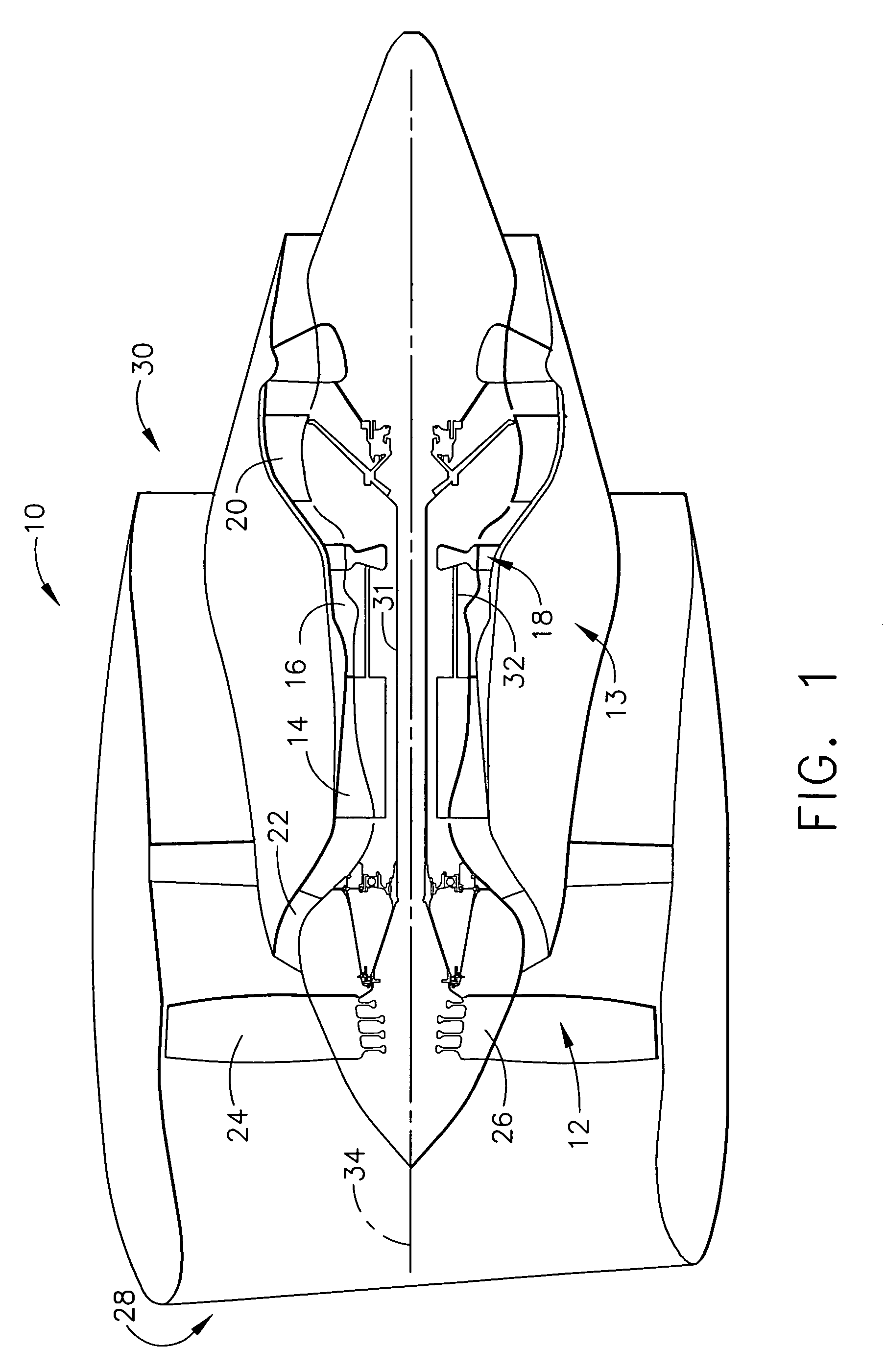
[0012]FIG. 1 is a schematic illustration of a gas turbine engine 10 including a fan assembly 12, a high pressure compressor 14, and a combustor 16. Engine 10 also includes a high pressure turbine 18, a low pressure turbine 20, and a booster 22. Fan assembly 12 includes an array of fan blades 24 extending radially outward from a rotor disc 26. Engine 10 has an intake side 28 and an exhaust side 30.

[0013]In operation, air flows through fan assembly 12 and compressed air is supplied to high pressure compressor 14. The highly compressed air is delivered to combustor 16. Airflow (not shown in FIG. 1) from combustor 16 drives turbines 18 and 20, and turbine 20 drives fan assembly 12.

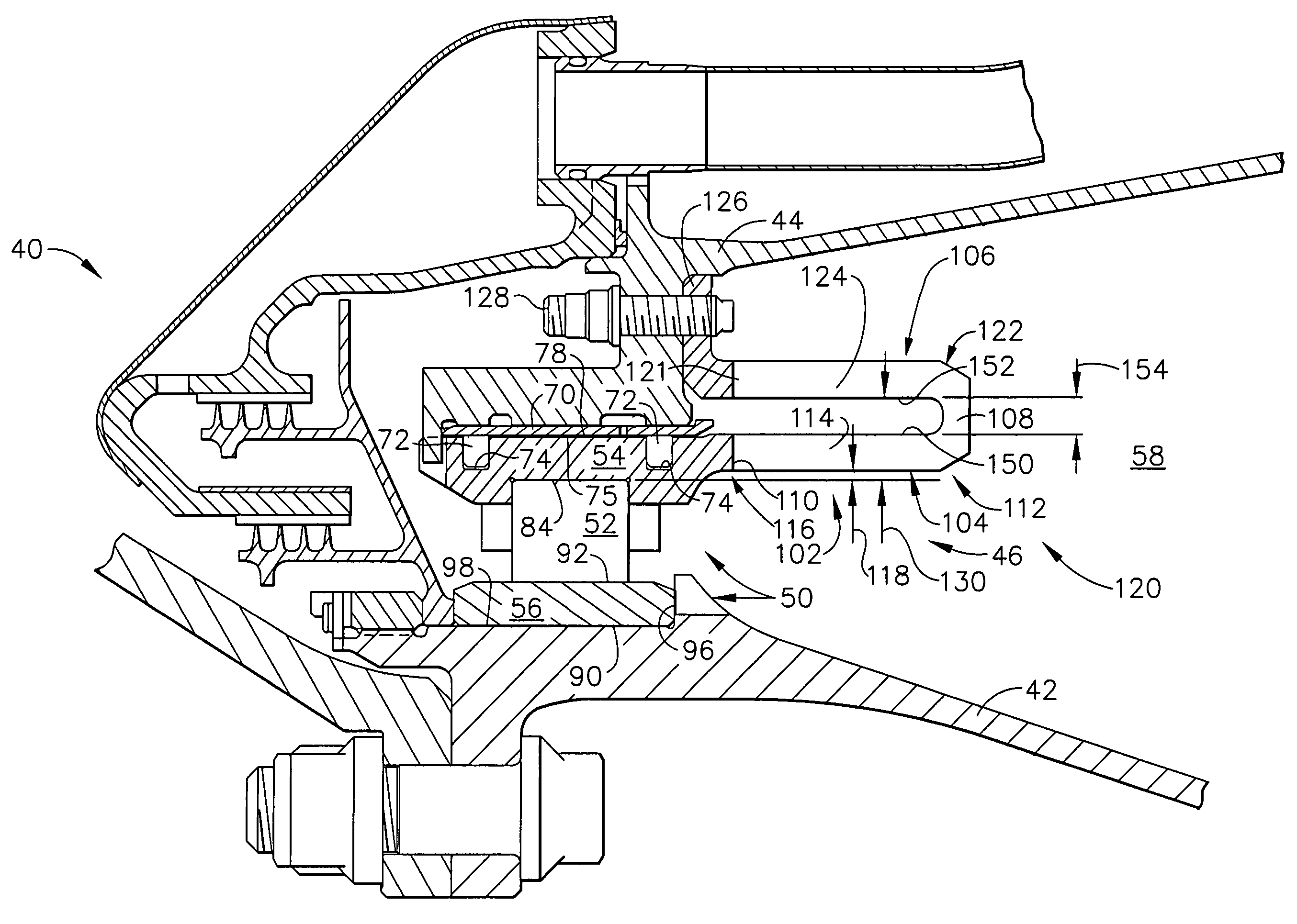
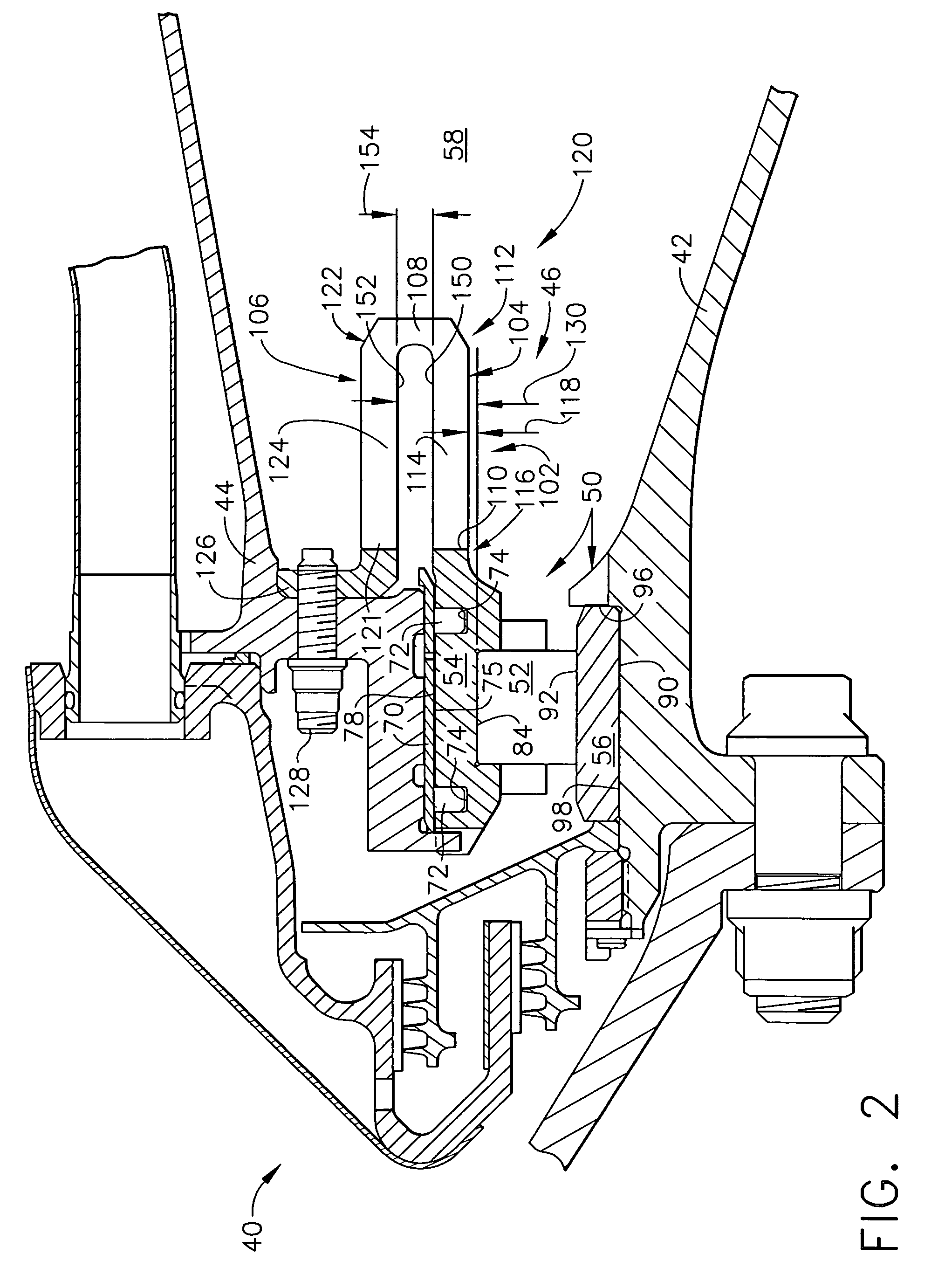
[0014]FIG. 2 is a cross-sectional view of an exemplary embodiment of a rotor and bearing assembly 40 that may be used with a gas turbine engine, such as engine 10 shown in FIG. 1. In one embodiment, the gas turbine engine is a GE90 available from General Electric Company, Cincinnati, Ohio. Rotor and bearing as...


PUM


Abstract

A bearing assembly for a gas turbine engine rotor includes, in an exemplary, an inner race, an outer race assembly, and a rolling element. The outer race assembly includes a body, a plurality of first springs attached to the body, and a plurality of second springs. Each first spring is radially aligned with a corresponding second spring forming a spring pair. The outer race assembly also includes a plurality of connecting members. Each connecting member extends between and connects a first end of the first spring and a first end of the second spring of said spring pair. The outer race assembly further includes a flange with each second spring attached to the flange.

Description

BACKGROUND OF THE INVENTION[0001]This application relates generally to gas turbine engine rotor assemblies and, more particularly, to bearing assemblies for gas turbine engine rotor assemblies.[0002]Gas turbine engines typically includes a fan rotor assembly, a compressor, and a turbine. The fan rotor assembly includes a fan including an array of fan blades extending radially outward from a rotor shaft. The rotor shaft transfers power and rotary motion from the turbine to the compressor and the fan, and is supported longitudinally with a plurality of bearing assemblies. Bearing assemblies support the rotor shaft and typically include rolling elements located within an inner race and an outer race.[0003]Additionally, at least some known bearing assemblies include a plurality of identical springs attached to the bearing outer race. The springs are spaced equally in a single row circumferentially around the rotor shaft to provide a discrete radial stiffness to the bearing and to center...

Claims


Application Information

Patent Timeline
Patent Type & Authority Patents(United States)
IPC IPC(8): F16C27/04
CPCF01D25/164F16C27/04F05D2230/64F16C2360/23F16C19/26F16C27/045
Inventor ALLMON, BARRY LYNNRIFFLE, RICHARD LEONCABE, JERRY LYNNANSTEAD, DUANE HOWARD
Owner GENERAL ELECTRIC CO
Why Eureka
Try Eureka