Charged particle beam extraction system and method

a particle beam and extraction system technology, applied in the field of charged particle beam extraction system and method, can solve the problem of not having established a real-time confirmation method, and achieve the effect of increasing safety and increasing safety in irradiation for treatmen

Active Publication Date: 2008-06-10
HITACHI LTD
View PDF8 Cites 125 Cited by
  • Summary
  • Abstract
  • Description
  • Claims
  • Application Information

AI Technical Summary

Benefits of technology

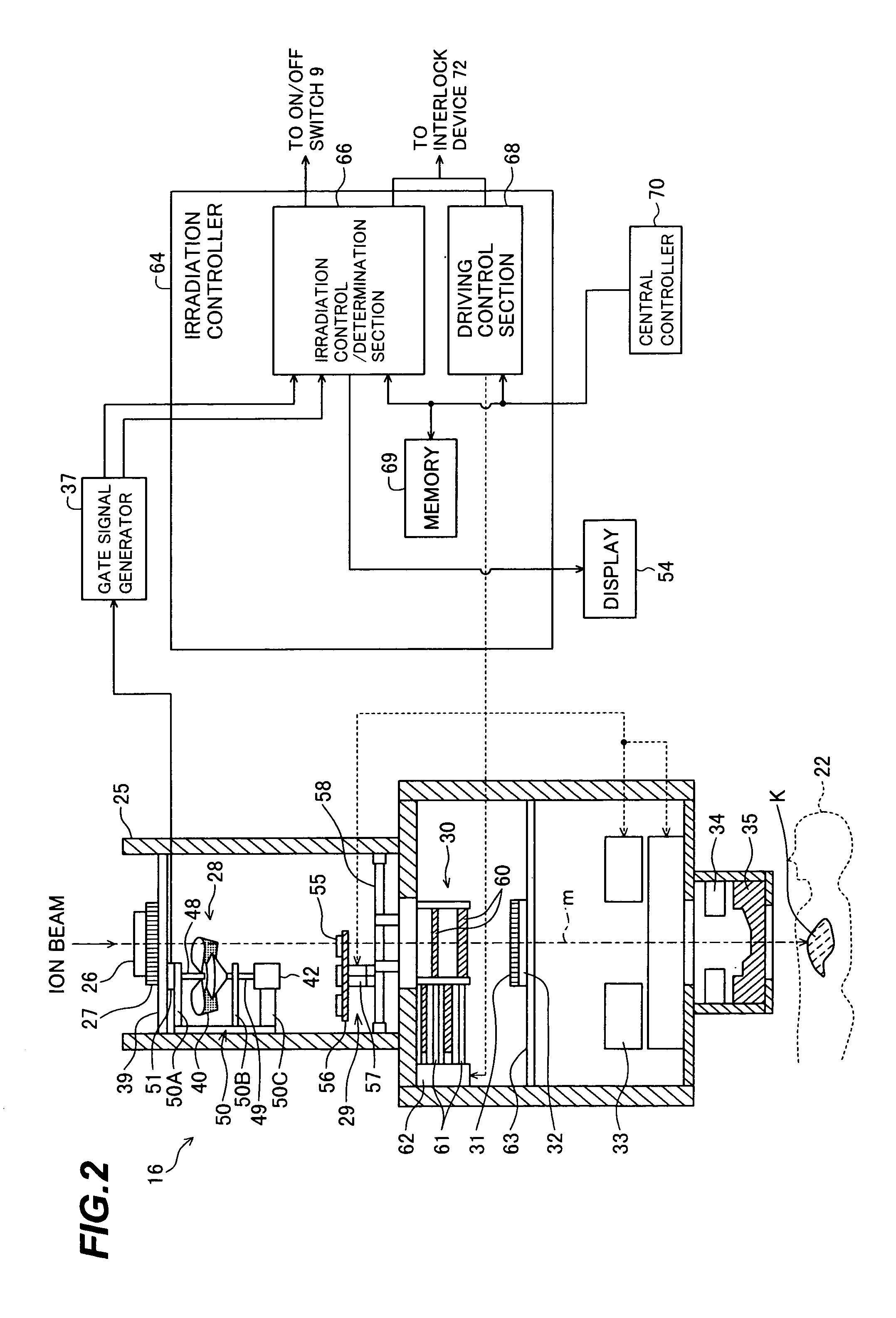
[0008]One of three inventors of this application has previously invented and filed a charged particle beam extraction system for performing on / off-control of extraction of an ion beam from a synchrotron during the rotation of the RMW. With that preceding invention, by rotating the RMW such that the ion beam passes the RMW for a comparatively long time, i.e., over a wider range of RMW rotational angle, the attenuation of the ion beam is varied to a large extent, and hence the SOBP width is increased. On the other hand, by rotating the RMW such that the ion beam passes the RMW for a comparatively short time, i.e., over a narrower range of RMW rotational angle, the attenuation of the ion beam is varied to a small extent, and hence the SOBP width is decreased. Thus, the on / off-control of extraction of the ion beam during the rotation of the RMW enables the SOBP width to be produced in various values by using one RMW. It is therefore possible to reduce the frequency at which the RMW is to be replaced, and to smoothly carry out the treatment for a larger number of patients.
[0010]According to the preceding invention, by performing the on / off-control of the beam extraction for each patient, the SOBP width can be obtained depending on the tumor in the body of the relevant patient. However, there has not yet been established a method for confirming in real time during the beam irradiation whether the beam is turned on and off at the desired timing. In other words, a further improvement is demanded from the viewpoint of ensuring higher safety in treatment.
[0011]It is an object of the present invention to provide a charged particle beam extraction system and method, which are able to ensure higher safety when extraction of an ion beam is on / off-controlled during irradiation of the ion beam for treatment.
[0013]With the present invention, since whether the start and stop of extraction of the charged particle beam is controlled at the desired timing during irradiation for treatment is determined, safety in the irradiation for treatment can be increased.
[0014]Preferably, the system is controlled so as to stop the extraction of the charged particle beam when it is determined that the start and stop of extraction of the charged particle beam is not controlled at the desired timing. This feature contributes to positively increasing safety in the treatment using the charged particle beam irradiated to the irradiation target.
[0015]Thus, according to the present invention, higher safety can be ensured in the treatment using the charged particle beam irradiated to the irradiation target.

Problems solved by technology

However, there has not yet been established a method for confirming in real time during the beam irradiation whether the beam is turned on and off at the desired timing.

Method used


Image

  • Charged particle beam extraction system and method
  • Charged particle beam extraction system and method
  • Charged particle beam extraction system and method

Examples


second embodiment

[0093]A charged particle beam extraction system according to another embodiment of the present invention will be described below with reference to FIGS. 11 and 12. In the charged particle beam extraction system of this second embodiment, the irradiation control / determination section 66 of the irradiation controller 64 in the above-described first embodiment, which measures the times Tp, T1 and T2 by using the timers, is replaced by an irradiation control / determination section (determination unit and third control unit) 66A which utilizes internal or external clocks and measures the times Tp, T1 and T2 by counting the internal or external clocks.

[0094]FIG. 11 is a time chart showing the relationship between the rotation of the RMW 40 and the gate signal in this second embodiment, and FIG. 12 is a functional block diagram showing the determining function of the irradiation control / determination section 66A. In FIGS. 11 and 12, similar components to those in FIGS. 7 and 8 are denoted b...

third embodiment

[0100]A charged particle beam extraction system according to still another embodiment of the present invention will be described below with reference to FIGS. 13 through 15. In the charged particle beam extraction system of this third embodiment, the irradiation control / determination sections 66, 66A of the irradiation controllers 64, 64A in the above-described first and second embodiments, which measure the times Tp, T1 and T2 by using the timers or the counter and comparing the measured values with the target values to make the determinations, is replaced by an irradiation control / determination section (determination unit and third control unit) 66B which executes the comparisons and the determinations by using memory data having addresses capable of being updated. Further, another gate signal generator is additionally provided.

[0101]FIG. 13 is a vertical sectional view showing a detailed structure of an irradiation apparatus in a charged particle beam extraction system according ...

fourth embodiment

[0107]A charged particle beam extraction system according to still another embodiment of the present invention will be described below with reference to FIG. 16. In the charged particle beam extraction system of this fourth embodiment, another gate signal generator is additionally provided as in the above-described third embodiment. Further, the irradiation control / determination section 66 of the irradiation controllers 64 in the above-described first embodiment is replaced by an irradiation control / -determination section (determination unit and third control unit) 66C which compares the gate signals from the two gate signal generators, as they are, for determination of the gate timing.

[0108]FIG. 16 is a functional block diagram showing the determining function of the irradiation control / -determination section 66C in this fourth embodiment. In FIG. 16, similar components to those in FIG. 15, etc. are denoted by the same symbols and a description of those components is omitted here.

[...


PUM

PropertyMeasurementUnit
energyaaaaaaaaaa
thicknessaaaaaaaaaa
rotational angleaaaaaaaaaa

Abstract

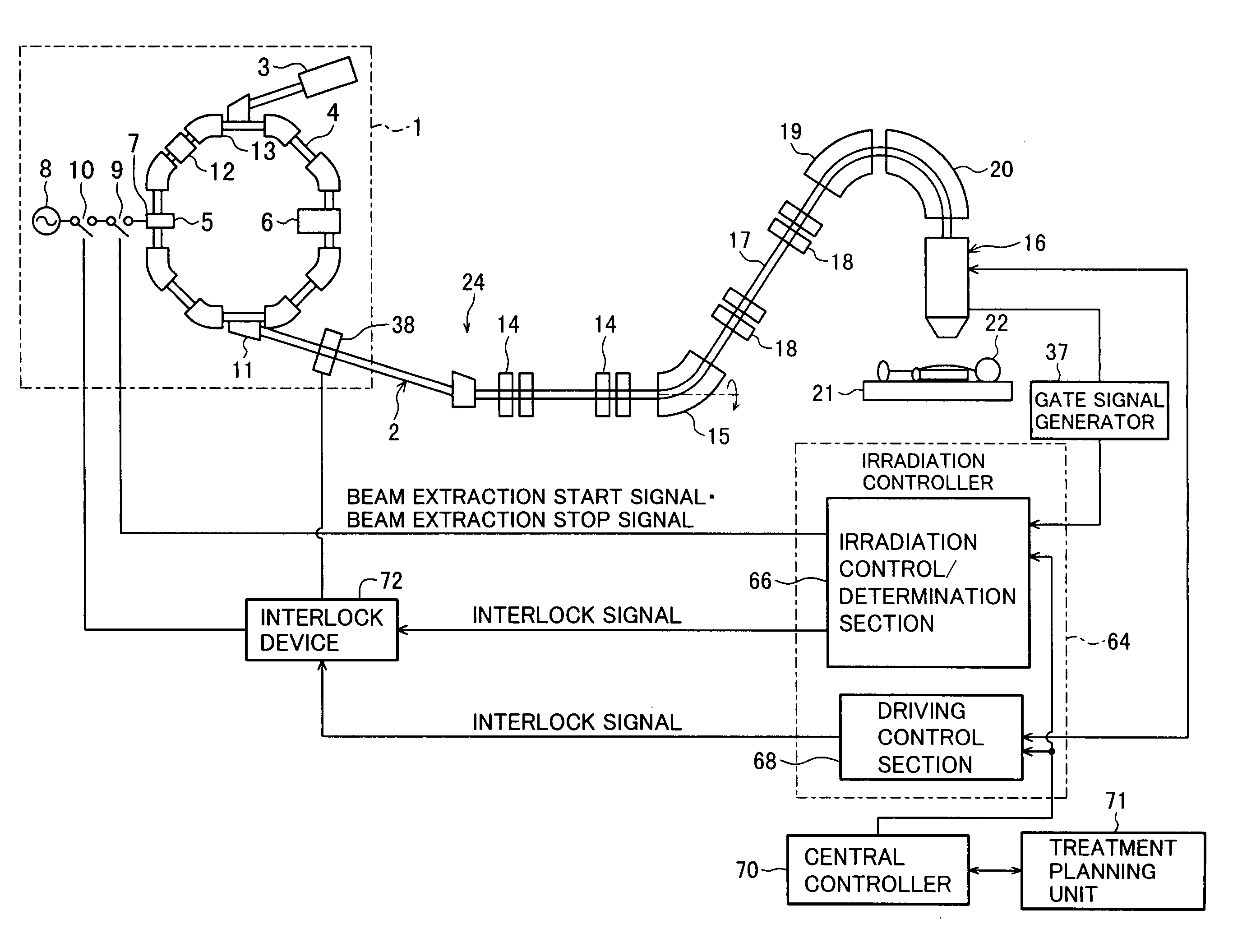
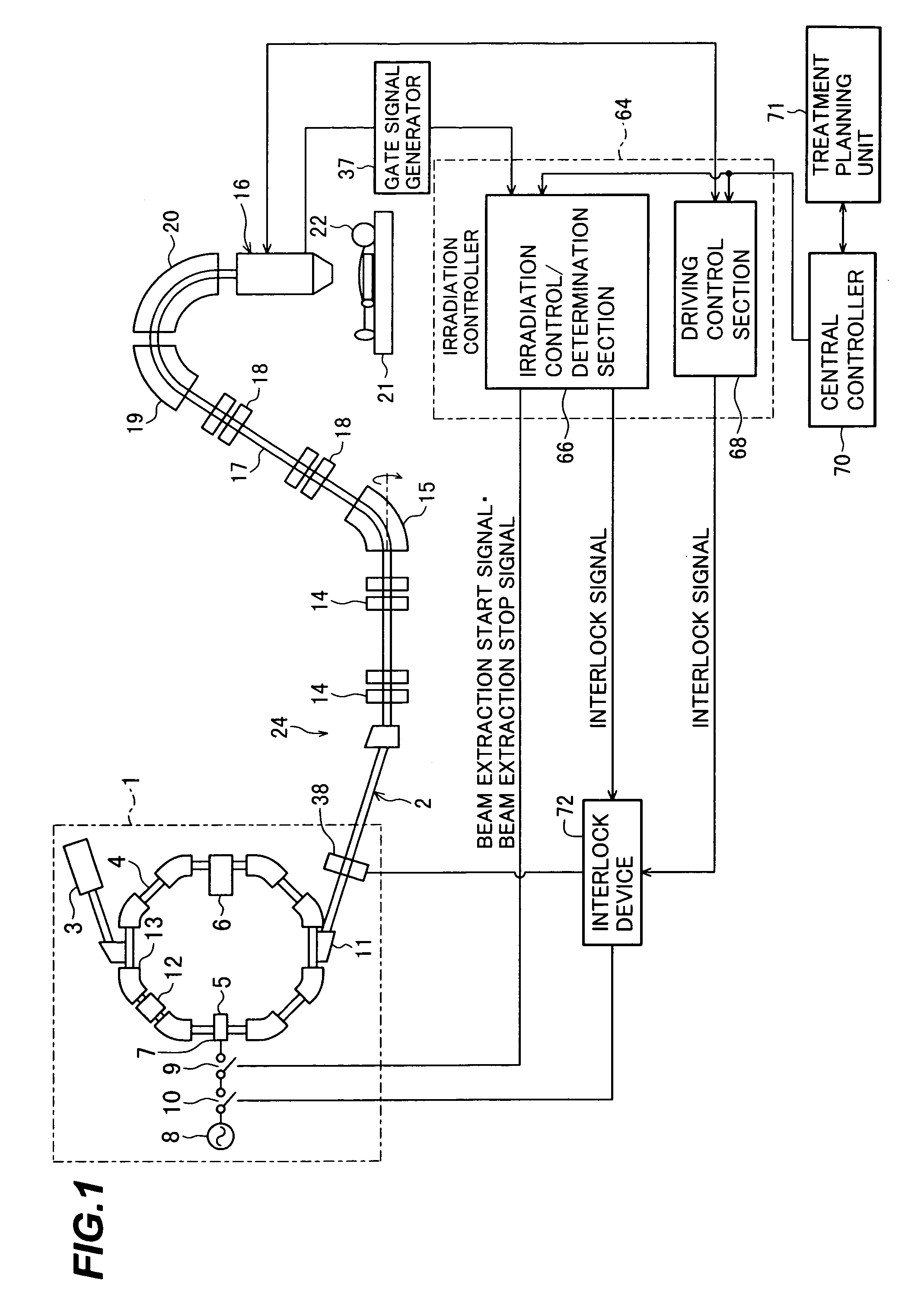
A charged particle beam extraction system and method capable of ensuring higher safety when extraction of an ion beam is on / off-controlled during irradiation of the ion beam for treatment. The charged particle beam extraction system comprises a charged particle beam generator including a synchrotron, a range modulation wheel (RMW) for forming a Bragg peak width of a charged particle beam extracted from the charged particle beam generator, a gate signal generator for controlling start and stop of extraction of the charged particle beam from the charged particle beam generator in accordance with a rotational angle of the RMW, and an irradiation control / determination section for determining whether the start and stop of extraction of the charged particle beam is controlled at desired timing by the gate signal generator.

Description

BACKGROUND OF THE INVENTION[0001]1. Field of the Invention[0002]The present invention relates to a charged particle beam extraction system and method for irradiating a charged particle beam, e.g., a proton or carbon ion beam, to a diseased part (represented by a tumor) for treatment.[0003]2. Description of the Related Art[0004]There is known a therapy method for irradiating a charged particle beam (ion beam), e.g., a proton or carbon ion beam, to a tumor such as a cancer in the body of a patient. A charged particle beam extraction system (ion beam extraction system) for use in such therapy comprises a charged particle beam generator, a beam transportation line, and an irradiation apparatus. An ion beam accelerated by the charged particle beam generator reaches the irradiation apparatus through a first beam transportation line and a second beam transportation line, the irradiation apparatus and the second beam transportation line being installed in a rotating gantry. The ion beam is ...

Claims


Application Information

Patent Timeline
Patent Type & Authority Patents(United States)
IPC IPC(8): G01K1/08H01J3/14H01J3/26
CPCH05H7/10A61N2005/1087
Inventor NAKAYAMA, TAKAHIDENATORI, TAKAYOSHIYANAGISAWA, MASAKI
Owner HITACHI LTD
Why Eureka
Try Eureka