Assembly structure for securing heat-dissipating fan

a technology for securing heat-dissipating fans and assembly structures, which is applied in the direction of lighting and heating apparatus, power cables, cables, etc., can solve the problems of troublesome and inconvenient fastening of fans, affecting the operation of servers, and generating a lot of heat within a tiny space, so as to save production costs and reduce production costs. , the effect of high industrial applicability

Inactive Publication Date: 2008-06-10
INVENTEC CORP
View PDF14 Cites 33 Cited by
  • Summary
  • Abstract
  • Description
  • Claims
  • Application Information

AI Technical Summary

Benefits of technology

[0008]Another objective of the present invention is to provide an assembly structure for securing a heat-dissipating fan so as to allow the heat-dissipating fan to be installed and removed rapidly and conveniently.
[0016]Accordingly, as abovementioned, the assembly structure of the present invention for securing the heat-dissipating fan, overcomes the drawbacks exiting in prior art as well as reduces the cost of production, and thus has high industrial applicability.

Problems solved by technology

Nowadays, a server is packed with a large amount of IC such as central processors or graphic chips in a tiny space, in order to increase processing speed and reduce space usage; however, operating these IC would also generate a lot of heat within a tiny space.
Moreover, the exterior of a server is usually packed with a casing for protection of the server system, however, such arrangement does not allow the heat generated from the interior of the server to be dissipated effectively, thereby influencing operation of the server.
The latter models of the heat-dissipating fan mostly require screwing components such as screws for fastening the fan in the server; however, a user may find it troublesome and inconvenient to fasten the fan via screwing during installation or removal.
However, as IC design and manufacturing technology have been improved day by day and integration density of IC have been increased constantly, a single heat-dissipating fan can no longer provide sufficient heat dissipation for rapidly and effectively dissipating heat generated from the interior of a server.

Method used


Image

  • Assembly structure for securing heat-dissipating fan
  • Assembly structure for securing heat-dissipating fan
  • Assembly structure for securing heat-dissipating fan

Examples


Embodiment Construction

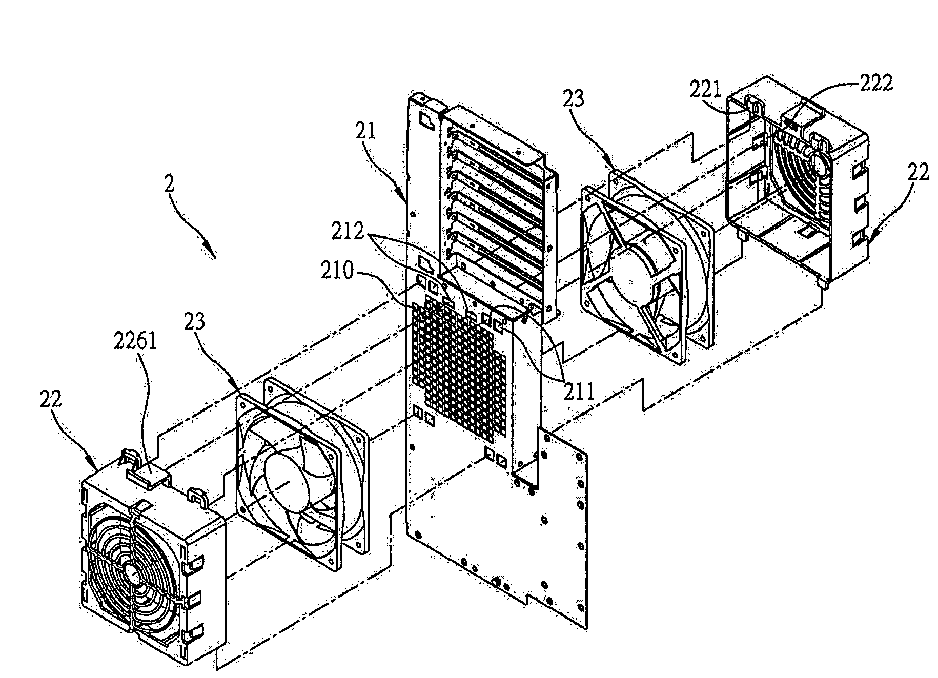
[0021]FIG. 2 is an exploded diagram showing an assembly structure for securing a heat-dissipating fan according to an exemplary preferred embodiment of the present invention. The assembly structure 2 for securing a heat dissipating fan, comprises a casing board 21 that may be a portion of a casing of an electronic device, and a fan covering 22 for storing and covering a heat-dissipating fan 23, wherein the casing board 21 of the electronic device is assembled to at least one of a server, a personal computer and an electronic device that can install a heat-dissipating fan on the casing thereof.

[0022]The casing board 21 is formed with at least a ventilation opening 210, at least a coupling opening 211 and at least a positioning opening 212. The fan covering 22 is formed with at least a coupling portion 221 and at least a positioning portion 222, secures the heat-dissipating fan 23 to a side of the casing board 21, wherein the coupling portion 221 is coupled to the coupling opening 211...


PUM


Abstract

An assembly structure provided for securing a heat-dissipating fan, includes a casing board and a fan covering for covering the fan, The casing board has ventilation openings, coupling openings and positioning openings, and the fan covering formed with coupling portions and positioning portions secures the fan to a side of the casing board, wherein the coupling portions are coupled to the coupling openings, and the positioning portions are positioned and coupled to the positioning openings, so that the fan is installed at a location allowing wind or airflow to pass through the ventilation openings. Arrangement as such, without using tools during assembling or dissembling processes, allows two heat-dissipating fans to be correspondingly coupled at both sides of the casing board, so as to increase wind force to increase heat dissipation in a simple but convenient way.

Description

FIELD OF THE INVENTION[0001]The present invention relates to assembly structures for securing heat-dissipating fans, and more particularly, to an assembly structure for a securing heat-dissipating fan of an electronic device.BACKGROUND OF THE INVENTION[0002]Following by improvements of the manufacturing technology for the integrated circuit (IC) design, the integration density of the IC increases continuously. Nowadays, a server is packed with a large amount of IC such as central processors or graphic chips in a tiny space, in order to increase processing speed and reduce space usage; however, operating these IC would also generate a lot of heat within a tiny space. Moreover, the exterior of a server is usually packed with a casing for protection of the server system, however, such arrangement does not allow the heat generated from the interior of the server to be dissipated effectively, thereby influencing operation of the server. Generally speaking, a simple and cheap but effectiv...

Claims


Application Information

Patent Timeline
Patent Type & Authority Patents(United States)
IPC IPC(8): H05K7/20
CPCH05K7/20172
Inventor LIN, LINGER
Owner INVENTEC CORP
Why Eureka
Try Eureka