Internal combustion engine with sidewall combustion chamber and method

a combustion chamber and sidewall technology, applied in the direction of combustion engines, reciprocating piston engines, positive displacement engines, etc., can solve the problems of using an unreasonable number of valves in critical situations, and the valves used in those engines must also operate, so as to achieve efficient and effective

Inactive Publication Date: 2008-06-17
HACSI JAMES SCOTT
View PDF11 Cites 22 Cited by
  • Summary
  • Abstract
  • Description
  • Claims
  • Application Information

AI Technical Summary

Benefits of technology

[0029]In accordance with the present invention, a novel internal-combustion, reciprocating-piston engine is presented that employs a combination of entirely new and beneficial concepts with older, proven concepts for the purpose of increasing the effectiveness and efficiency of internal combustion engines. Engines are contemplated that have fewer parts and are thus less complex, lighter in weight, cheaper-to-build, more reliable, and much more effective in reducing air pollution and decreasing fuel consumption by an automobile. Use of a sidewall combustion chamber, which is extended down along the outside-wall of the cylinder for minimizing volume and also containing the intake valve, the exhaust valve, and possibly a sparkplug, allows the engine to be kept cool during operation. The sidewall combustion chamber also gives the engine a previously unanticipated ability to receive air, or a mixture of fuel and air, from a cylinder at one location and re-inject a high-pressure mixture of burning fuel and air after ignition into the same cylinder at a more optimum location. The ability to efficiently use hydrogen as a fuel gives the engine known as the present invention an unprecedented advantage over any other engine in use today for allowing our country to move to a “hydrogen economy”. A displacer-piston is used in the present invention to minimize volume in the cylinder during the combustion process while the main piston moves substantially into its power-stroke as was previously done in the proven Fairbanks-Morse engines of the past.

Problems solved by technology

The Scuderi engine and both Negre engines, and any other split-cycle engine for that matter, seem to use an unreasonable number of valves in critical areas of operation.
Moreover, the valves used in those engines must also operate when subjected to severe heat and mechanical stress conditions.

Method used


Image

  • Internal combustion engine with sidewall combustion chamber and method
  • Internal combustion engine with sidewall combustion chamber and method
  • Internal combustion engine with sidewall combustion chamber and method

Examples


Embodiment Construction

—PREFERRED EMBODIMENT

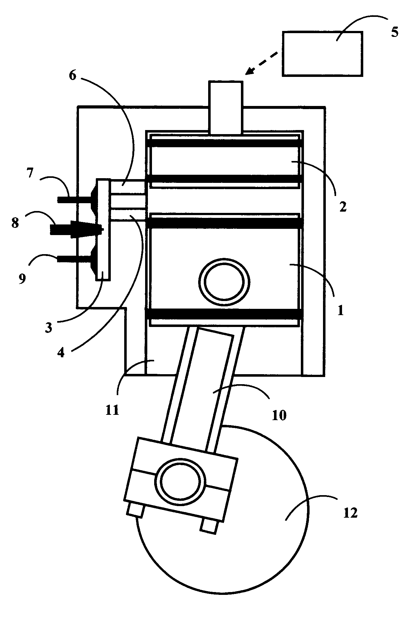
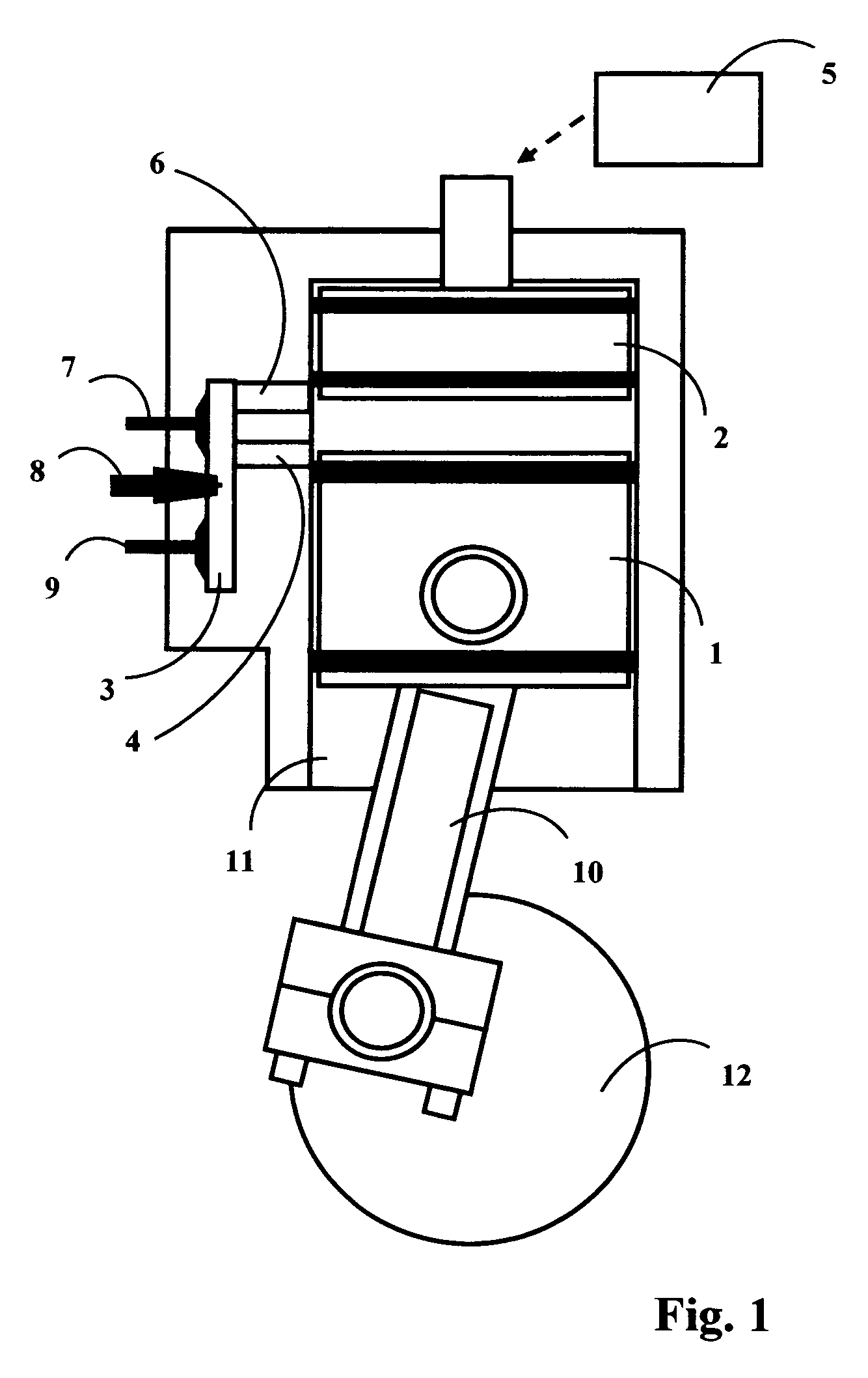
[0032]A detailed section of a preferred embodiment of the engine known as the present invention is shown in FIG. 1 with engine parts labeled for identification. A main piston 1 is contained in a cylinder 11 and is free to move within the cylinder while rings or seals on the outside diameter of the main piston 1 prevent gas leakage around the main piston 1. Also, in the same cylinder 11 and sharing the cylinder's volume is a displacer-piston 2 which is also free to move within the cylinder 11 and is sealed along its outside diameter with seals or rings to prevent gas leakage. The displacer-piston 2 which is driven by an actuating means 5 to allow it to slide up and down the cylinder and accompany the main piston 1 in its travel, occupies the top volume of the cylinder 11, where the “top” of the cylinder 11 implies the volume or space in the cylinder 11 closest to the cylinder's head and farthest away from the “bottom” of the cylinder 11, which is where the main p...


PUM


Abstract

An internal-combustion, reciprocating-piston engine operating on the Otto cycle and associated method are provided where a sidewall combustion chamber is employed that is capable of receiving highly-compressed air or a mixture of any gas and fuel from a cylinder while a main piston is positioned at or near top-dead-center in the cylinder, and where the sidewall combustion chamber is also capable of temporarily storing a highly-compressed air or a mixture of any gas and fuel before sending and re-injecting an ignited or burning mixture of highly-compressed air or a mixture of any gas and fuel into the same cylinder between the main piston and the displacer-piston when the main piston is located in the cylinder at an optimum position for receiving and transferring energy or forces.

Description

CROSS-REFERENCE TO RELATED APPLICATIONS[0001]This application claims the benefit of PPA Ser. No. 60 / 848,594 filed Oct. 02, 2006STATEMENT REGARDING FEDERALLY SPONSORED RESEARCH[0002]Not applicableSEQUENCE LISTING OR PROGRAM[0003]Not applicableBACKGROUND OF THE INVENTION[0004]1. Field of the Invention[0005]This invention relates to internal-combustion, reciprocating-piston engines and combustion processes used therein and more specifically, this invention relates to internal-combustion, reciprocating-piston engines which use a sidewall combustion chamber and a displacer-piston for improving output power and efficiency.[0006]2. Description of Prior Art[0007]Combustion normally occurs in common reciprocating-piston, internal combustion engines when the piston reaches the highest point in the cylinder in order to take advantage of maximum compression of the fuel / air mixture at the time of ignition. At that point, however, the piston's connecting rod is nearly vertically aligned with the ...

Claims


Application Information

Patent Timeline
Patent Type & Authority Patents(United States)
IPC IPC(8): F01B7/12F02B19/00
CPCF02B19/1066F02B21/00F02B75/042F02B25/14Y02T10/125Y02T10/12
Inventor HACSI, JAMES SCOTT
Owner HACSI JAMES SCOTT
Why Eureka
Try Eureka