Hydraulic valve actuation systems and methods to provide variable lift for one or more engine air valves

a technology of hydraulic valves and air valves, applied in the field of piston engines, can solve the problems of inability to provide the accuracy and uniformity of valve lift desired for smooth engine operation under all conditions, and the inability to provide a fixed relationship between crankshaft angle and valve position,

Active Publication Date: 2008-06-17
STURMAN INDS
View PDF29 Cites 21 Cited by
  • Summary
  • Abstract
  • Description
  • Claims
  • Application Information

AI Technical Summary

Problems solved by technology

While such systems are in a high state of development and usually provide reliable performance for the life of the engine, they have the disadvantage of providing a fixed relationship between crankshaft angle and valve position.
Accordingly, the timing for valve opening and closing, the valve lift obtained, etc., are predetermined and fixed throughout the operating range of the engine, thus providing a substantial engine performance compromise under most engine operating conditions.
This, in theory, provides the desired result, though in practice may not provide the accuracy and uniformity in valve lift desired for smooth engine operation under all conditions.
This has certain advantages, but also adds to the complexity of the system.
In engines with multiple intake and / or exhaust valves per cylinder, a common engine valve actuator for the multiple valves of each type would need to be used, as typically the control would be common for economic reasons, and separate actuators may not track each other that well.
Also, the control would need to be closed loop in real time for each actuator, preferably with a self adapting capability based on feedback of the actual lift obtained on the last engine cycle, making the control algorithm complicated and limiting the accuracy achieved by the limited speed of the control valving.

Method used


Image

  • Hydraulic valve actuation systems and methods to provide variable lift for one or more engine air valves
  • Hydraulic valve actuation systems and methods to provide variable lift for one or more engine air valves
  • Hydraulic valve actuation systems and methods to provide variable lift for one or more engine air valves

Examples


Embodiment Construction

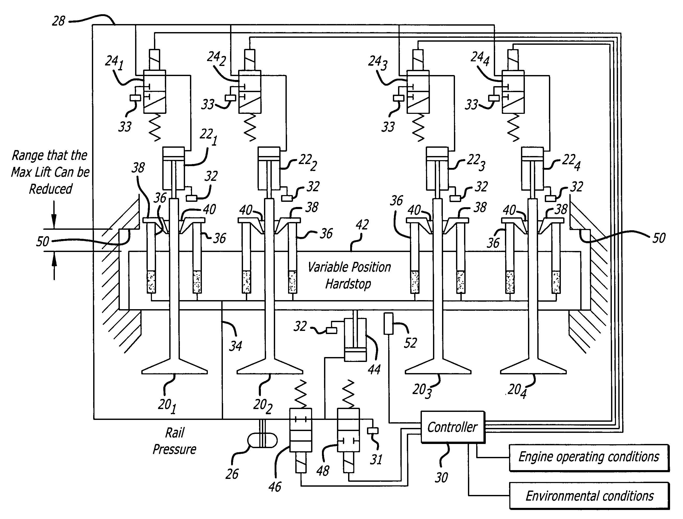
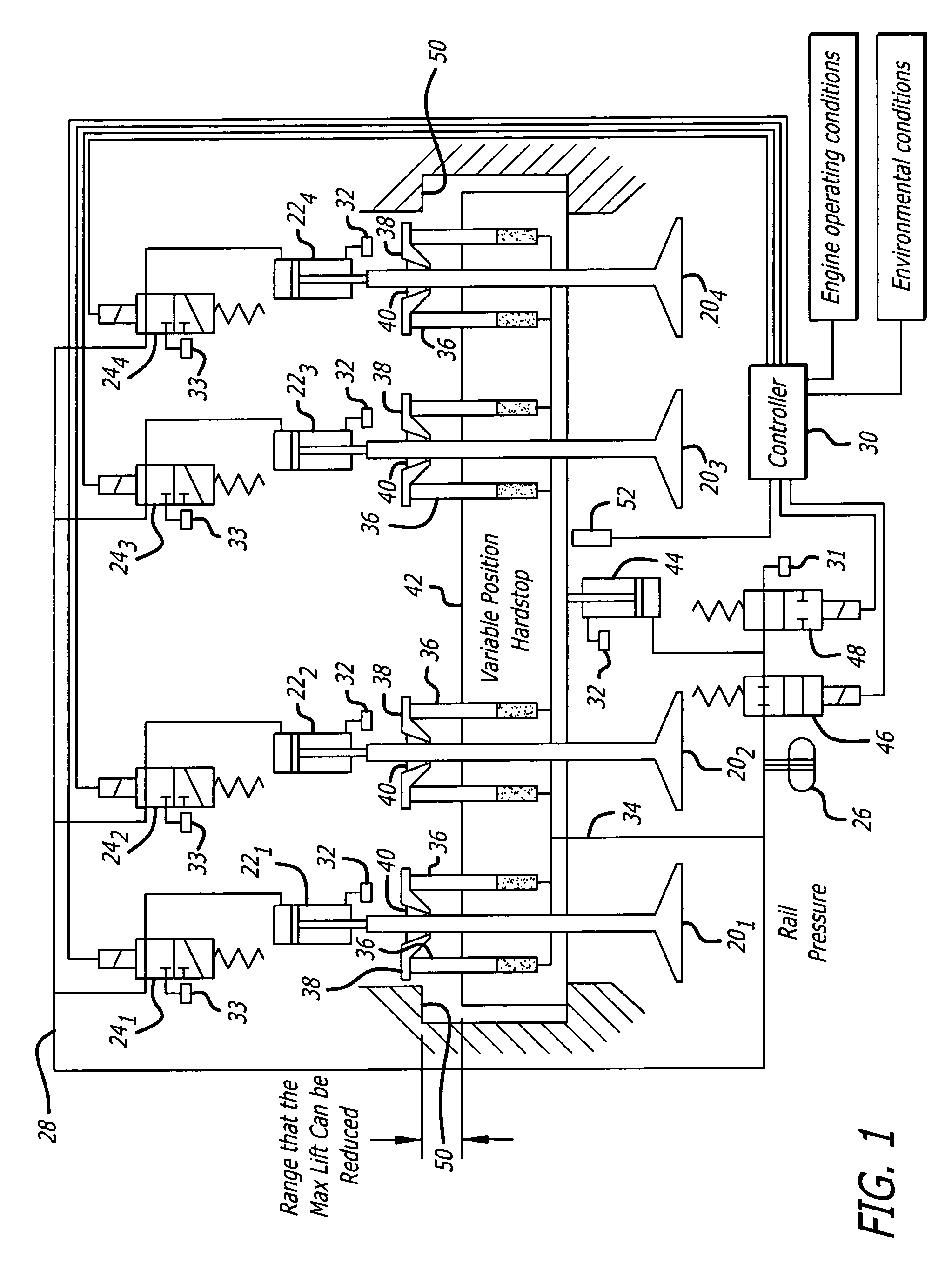
[0021]First referring to FIG. 1, a schematic diagram of a preferred embodiment of the present invention may be seen. This schematic provides a good overview of an embodiment of the present invention, though as shall subsequently be seen, various details of preferred forms of various elements of FIG. 1 providing specific implementations and additional capabilities and features are not explicitly shown in FIG. 1.

[0022]FIG. 1 illustrates four engine valves 201, 202, 203 and 204, each actuated by a respective hydraulic actuator 221, 222, 223 and 224, in turn controlled by three-way valves 241, 242, 243 and 244. The control valves 24 in the preferred embodiment are coupled to a high pressure rail 26 through line 28, the three-way control valves in the embodiment illustrated being single solenoid spring return spool valves controlled by controller 30, though other types of valves may be used as desired, such as double solenoid magnetically latching or non-latching, single solenoid hydraul...


PUM


Abstract

Hydraulic valve actuation systems and methods to provide variable lift for one or more engine air valves by way of a variable position hard stop. Various embodiments are disclosed, including embodiments controlling lift by providing a choice of two different fixed stops, three different fixed stops, stops continuously variable throughout a range of lifts, and a fixed stop and stops continuously variable throughout a range of lifts. The valves controlled by a variable position hard stop may be a single engine intake or exhaust valve, or multiple valves of any number, and of either intake or exhaust valves or both, or of one intake or one exhaust valve for one or more cylinders in engines having more than one intake or exhaust valve per cylinder. Dashpot deceleration of engine valve velocity on opening to the hard stop and on engine valve closure is disclosed, as are other aspects and embodiments of the invention.

Description

CROSS-REFERENCE TO RELATED APPLICATION[0001]This application claims the benefit of U.S. Provisional Patent Application No. 60 / 560,561 filed Apr. 8, 2004.BACKGROUND OF THE INVENTION[0002]1. Field of the Invention[0003]The present invention relates to the field of piston engines.[0004]2. Prior Art[0005]Historically, piston engines have used mechanically actuated poppet type intake and exhaust valves operated by way of an engine driven camshaft. While such systems are in a high state of development and usually provide reliable performance for the life of the engine, they have the disadvantage of providing a fixed relationship between crankshaft angle and valve position. Accordingly, the timing for valve opening and closing, the valve lift obtained, etc., are predetermined and fixed throughout the operating range of the engine, thus providing a substantial engine performance compromise under most engine operating conditions.[0006]More recently, considerable work has been done in the dev...

Claims


Application Information

Patent Timeline
Patent Type & Authority Patents(United States)
IPC IPC(8): F01L9/02F01L9/10
CPCF01L9/02F01L2009/0436F01L2009/2136F01L9/10
Inventor BABBITT, GUY ROBERTRAIMAO, MIGUEL ANGELOKLOSE, CHARLES CONRADROGERS, JEFFREY ALLENSTURMAN, ODED EDDIE
Owner STURMAN INDS
Why Eureka
Try Eureka