Processing apparatus and substrate processing method

a processing apparatus and substrate technology, applied in the direction of chemistry apparatus and processes, cleaning using liquids, coatings, etc., can solve the problems of increasing the installation cost, and affecting the effect of substrate processing efficiency

Inactive Publication Date: 2008-06-17
TOKYO ELECTRON LTD
View PDF10 Cites 79 Cited by
  • Summary
  • Abstract
  • Description
  • Claims
  • Application Information

AI Technical Summary

Benefits of technology

[0006]Under such a circumference as mentioned above, an object of the present invention is to provide substrate processing apparatus and method by which it becomes possible to realize both space-saving and low cost about the installation of the apparatus with a reduced influence of the particles on a substrate.

Problems solved by technology

However, if the apparatus is provided with respective rotating mechanisms to rotate the wafer and the top-face member individually, then the apparatus becomes big to increase its installation cost.
Additionally, if the rotating mechanism to rotate the top-face member is arranged above the “substrate-processing” position, it is feared that particles from the rotating mechanism invade the surroundings of the wafer.
Also, if an actuating cylinder for moving the top-face member up and down is disposed above the “substrate-processing” position, then there is a fear that particles from the actuating cylinder invade the surroundings of the wafer, as well.

Method used


Image

  • Processing apparatus and substrate processing method
  • Processing apparatus and substrate processing method
  • Processing apparatus and substrate processing method

Examples


first embodiment

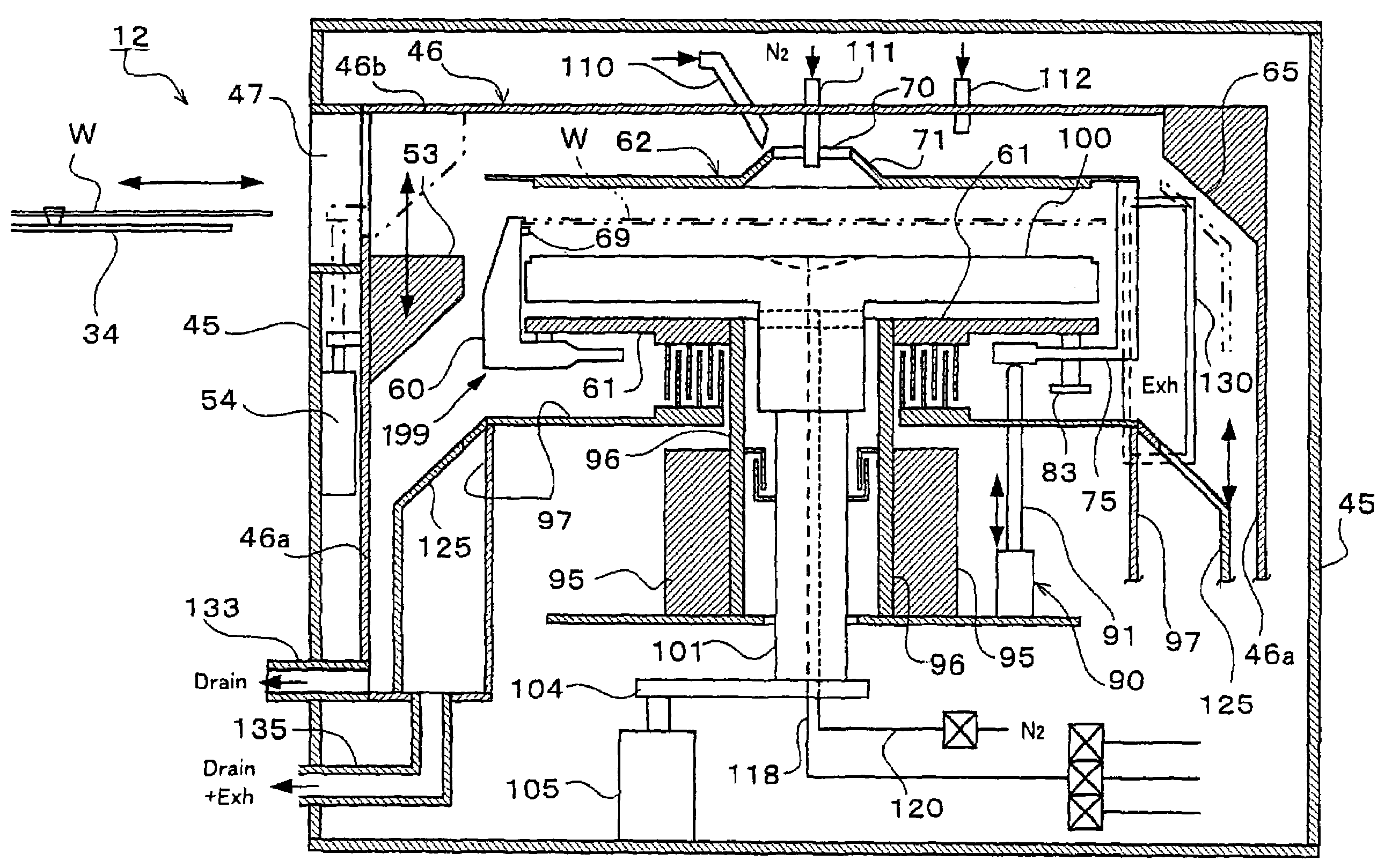
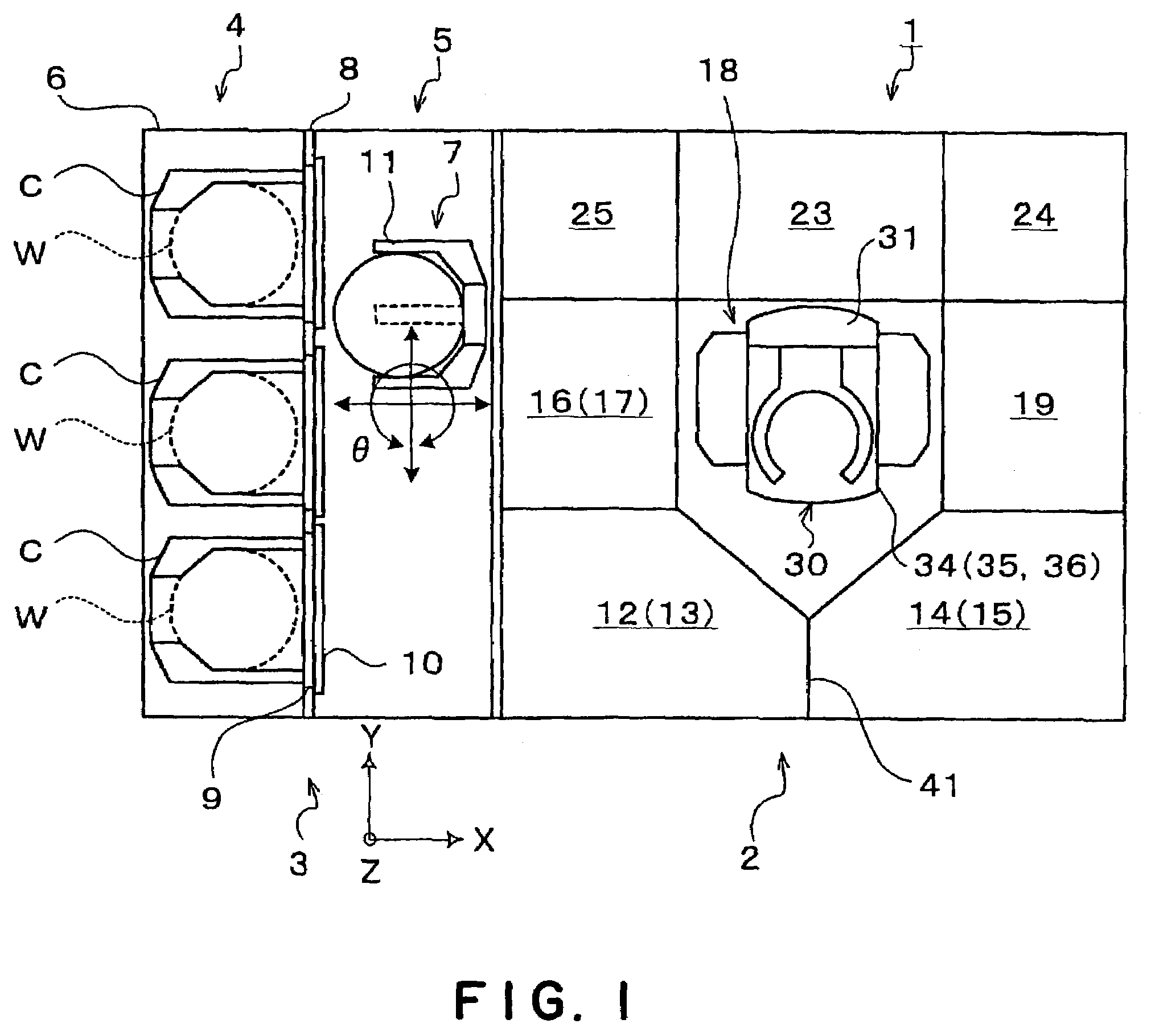
[0080]FIG. 3 is a plan view of the substrate cleaning unit 12 in accordance with the present invention. A unit chamber 45 of the substrate cleaning unit 12 includes an outer chamber 46 in which the wafer W is accommodated for processing with a processing fluid, forming a substrate processing part. The outer chamber 46 is adapted so as to surround the wafer W from its vicinity and upside. The outer chamber 46 has a annular sidewall 46a for surrounding the circumference of the wafer W and a ceiling part 46b for covering the upside of the wafer W to isolate an atmosphere about and above the wafer W from an atmosphere outside the outer chamber 46. The unit chamber 45 has an opening 50, while the outer chamber 46 has an opening 52 formed in the sidewall 46a to communicate with the opening 50 through an opening 47. The outer chamber 45 is provided with an “outer-chamber” mechanical shutter 53 that can open and close the opening 52 owing to a cylinder driving mechanism 54 consisting of an ...

second embodiment

[0125]Next, we describe the substrate cleaning unit in accordance with the invention.

[0126]FIG. 10 is a plan view of a substrate cleaning unit 212 in accordance with the second embodiment. FIG. 11 is a longitudinal sectional view of the substrate cleaning unit 212. A unit chamber 245 of the substrate cleaning unit 212 includes an outer chamber 246 that accommodates the wafer W and process it with a processing fluid. The unit chamber 45 has an opening 250 formed therein, while the outer chamber 246 has an opening 252 formed in its sidewall 246a. The opening 252 is communicated with the opening 50 through an opening 247. The outer chamber 245 is provided with a mechanical shutter 253 that is driven by a cylinder driving mechanism 254 consisting of an air cylinder etc. to move up and down thereby opening and closing the opening 252. For example, when the transfer arm 234 transfers the wafer W into or from the outer chamber 246 through the opening 247, the mechanical shutter 253 opens. ...


PUM

PropertyMeasurementUnit
heightaaaaaaaaaa
widthaaaaaaaaaa
widthaaaaaaaaaa

Abstract

A substrate processing apparatus for processing a substrate With a processing fluid is provided. The apparatus includes holding members 60 for holding the substrate W, a chuck member 61 for supporting the holding members 60 and a top-face member 62 approaching the substrate W to cover its surface. In arrangement, since the top-face member 62 is supported by the chuck member 61, the holding members 60 can rotate together with the top-face member 62 in one body. With this structure, it is possible to reduce the influence of particles on the substrate W and also possible to provided a low-cost substrate processing apparatus occupied as little installation space as possible.

Description

BACKGROUND OF THE INVENTION[0001]1. Technical Field of the Invention[0002]This invention relates to substrate processing apparatus and method for processing (e.g. cleaning) a substrate, for example, semiconductor wafer, glass for LCD substrate, etc.[0003]2. Description of the Related Art[0004]In the manufacturing process of semiconductor devices, a processing system is used to apply a specific processing (e.g. cleaning, removing of resist film) on the surfaces of a semiconductor water. Noted that the semi conductor water will be referred “wafer”, hereinafter. As a substrate processing apparatus provided in the above processing system, there is known a single wafer processing apparatus adapted to supply a processing liquid to a wafer being held horizontally. In view of the prevention of contamination of a wafer by particles and also the reduction of consumption of the processing liquid, the conventional single wafer processing apparatus is provided with a plate-shaped top-face member...

Claims


Application Information

Patent Timeline
Patent Type & Authority Patents(United States)
IPC IPC(8): B08B3/00B05C11/00B05C11/02B05C13/00B05C13/02B05C5/00B05C7/06B08B3/12B08B6/00H01L21/00H01L21/687
CPCH01L21/67051H01L21/68792H01L21/68728H01L21/6719H01L21/304
Inventor KURODA, OSAMUTANIYAMA, HIROKITOSHIMA, TAKAYUKI
Owner TOKYO ELECTRON LTD
Why Eureka
Try Eureka