Cutting insert and a tool for chip removing machining, as well as an attachment for such tools

a technology for cutting inserts and tools, applied in the direction of cutting inserts, manufacturing tools, shaping cutters, etc., can solve the problems of difficult mastery of drawbacks, inability to rigidly fix cutting inserts in the insert seat of the basic body, and relative motions in the direction parallel to the ridges cannot be prevented, so as to reduce the requirements of dimensional accuracy

Active Publication Date: 2008-06-17
SANDVIK INTELLECTUAL PROPERTY AB
View PDF11 Cites 84 Cited by
  • Summary
  • Abstract
  • Description
  • Claims
  • Application Information

AI Technical Summary

Benefits of technology

[0006]The present invention aims at obviating the above-mentioned drawbacks and reducing the requirements on dimensional accuracy in connection with the manufacture of such cutting tools that make use of rigidly securing connecting surfaces in the interface between different components in the tool.

Problems solved by technology

However, relative motions in the direction parallel to the ridges are not prevented.
However, in practice, this solution—as well as similar solutions to the problem, which are based on the use of a greater number of force-carrying flank pairs—has turned out to be associated with drawbacks difficult to master.
However, as soon as a smallest form defect unintentionally arises in any single flank, there is a risk that the cutting insert cannot be rigidly fixed in the insert seat of the basic body.
In other words, the support of the cutting insert against the insert seat becomes over-determined, whereby the precision in respect of the position of the cutting edges in relation to the basic body is lost.

Method used


Image

  • Cutting insert and a tool for chip removing machining, as well as an attachment for such tools
  • Cutting insert and a tool for chip removing machining, as well as an attachment for such tools
  • Cutting insert and a tool for chip removing machining, as well as an attachment for such tools

Examples


Embodiment Construction

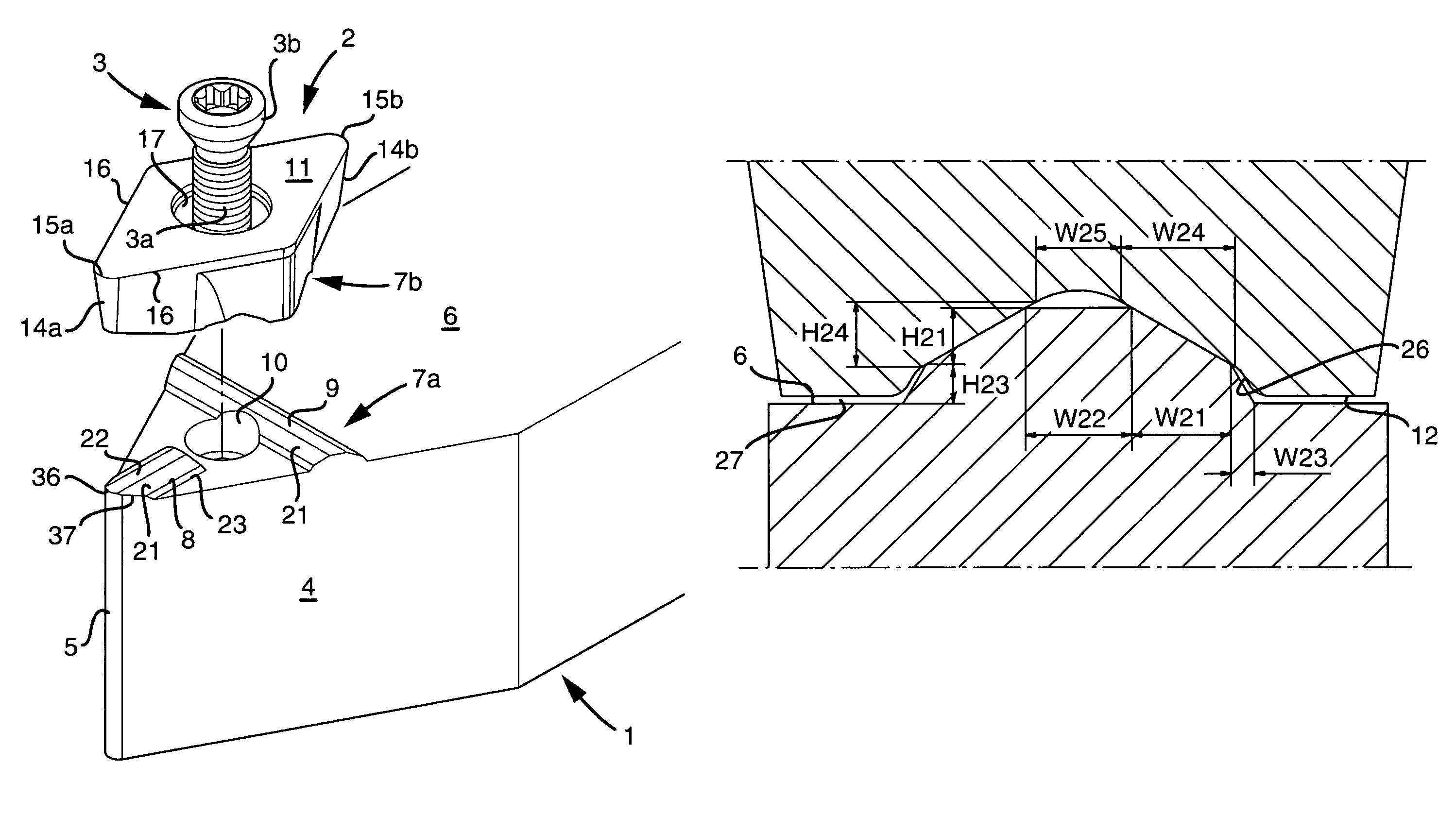
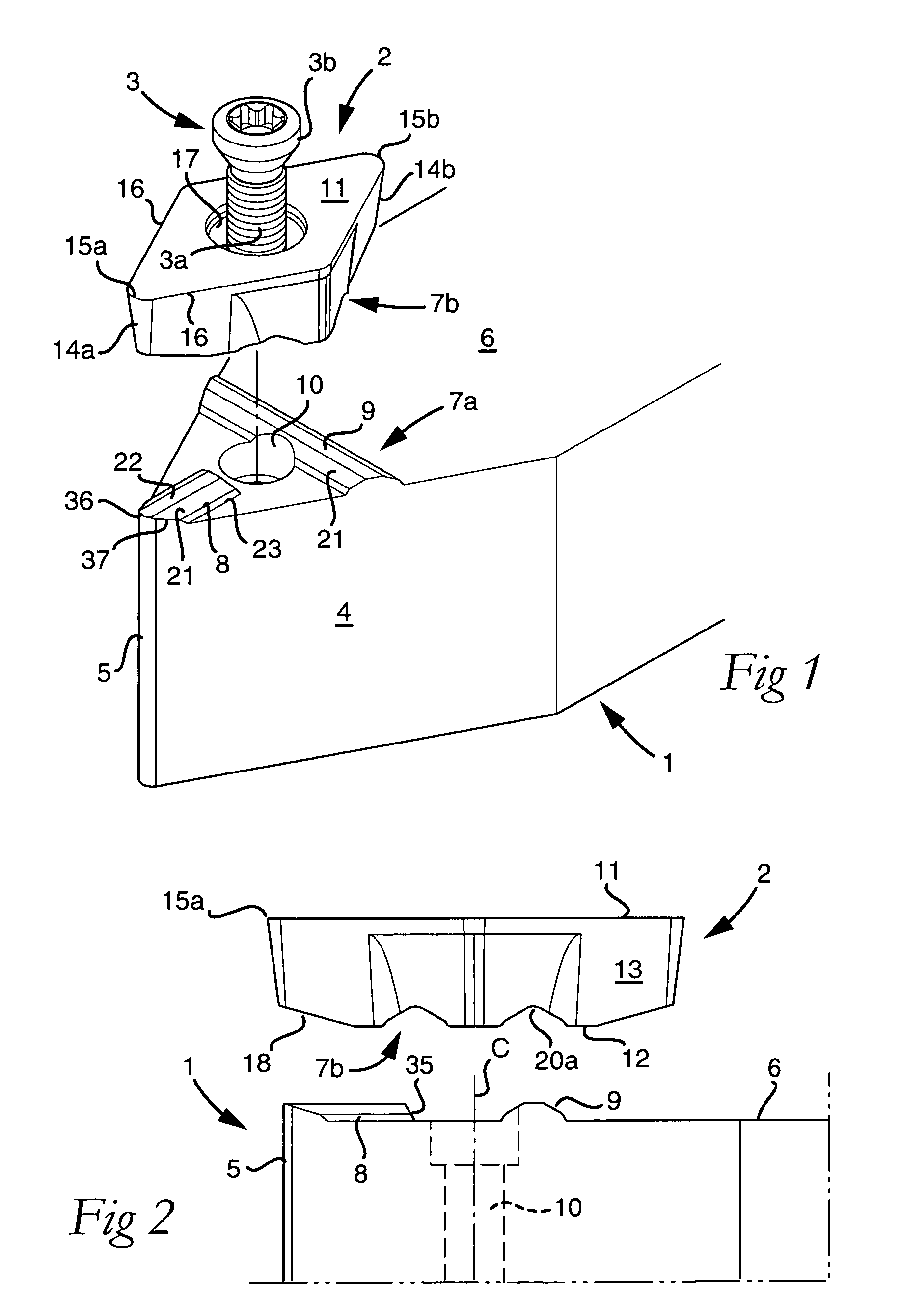
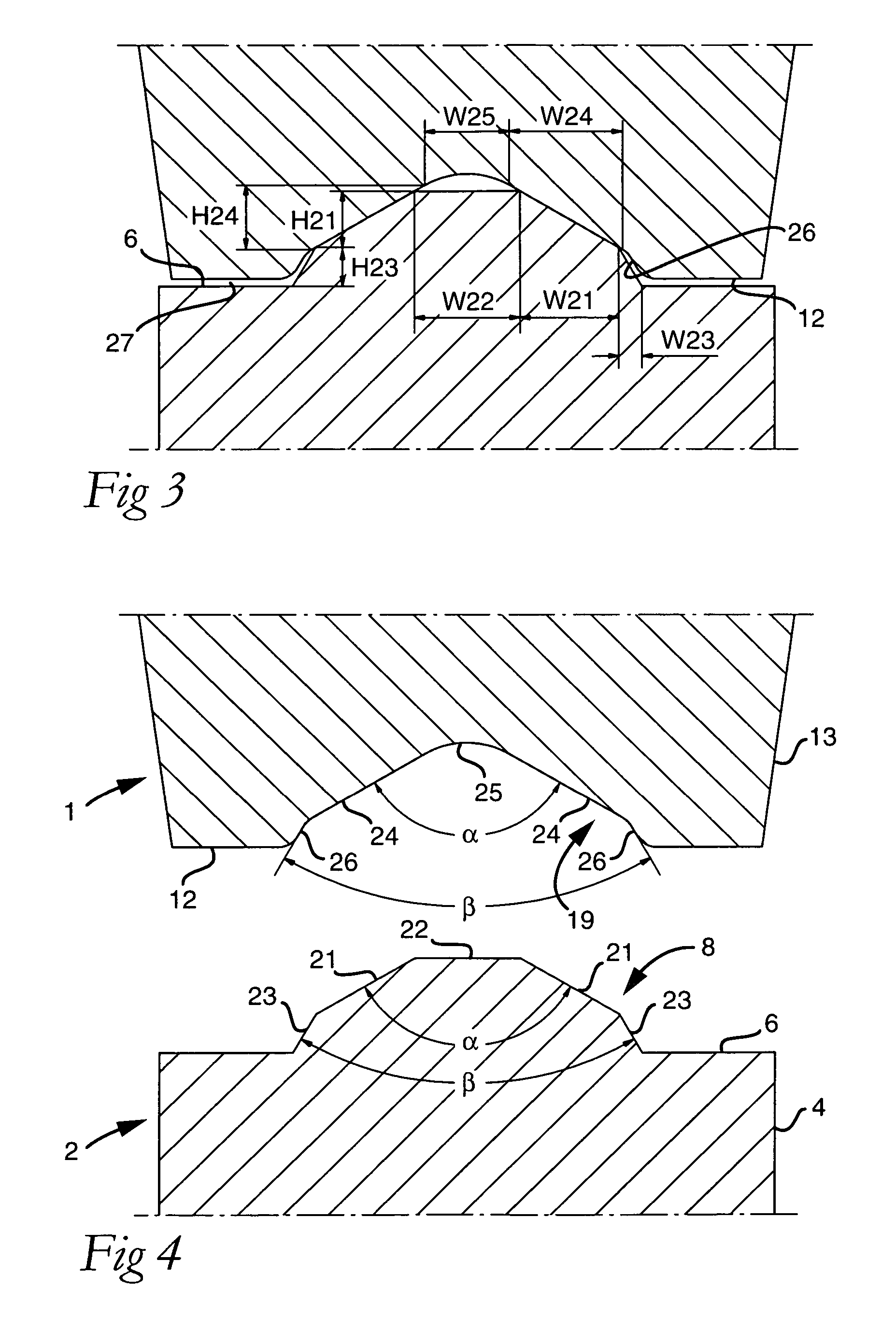
[0024]In FIGS. 1-7, a cutting tool is shown in the form of a turning tool, which in a conventional way includes a holder or basic body 1, as well as a cutting insert 2. For the fixation of the cutting insert, a tightening element 3 is used, which in the example is in the form of a screw, but which also could be a clamp. A front, free end of the basic body 1 tapers, via converging side surfaces 4, wedge-shapedly toward a nose 5. On the top side 6 of the basic body, which in this case is planar, a connecting surface, in its entirety designated 7a, is formed, which forms a so-called insert seat for the cutting insert 2. In the connecting surface 7a, engagement portions 8, 9 are included, which in this case are male-like. Furthermore, it should be noted that a threaded hole 10 mouths in the connecting surface.

[0025]The cutting insert 2 has a top side 11 and a bottom side 12 (see FIG. 2) between which a circumferential clearance surface 13 extends. In the example, the cutting insert is i...


PUM

PropertyMeasurementUnit
heightaaaaaaaaaa
heightaaaaaaaaaa
acute angleaaaaaaaaaa

Abstract

A cutting insert having a front cutting edge and a connecting surface including male- and / or female-like engagement portions, in order to rigidly secure the cutting insert, a geometrically predetermined reference locus serving as a force-application spot for the clamping of the cutting insert. Simultaneously active engagement portions are of only two types—a first, elongate engagement portion, which is located between the front cutting edge and the reference locus, and a second, elongate engagement means, which is oriented at an angle to the first engagement portion and situated at a greater distance from the front cutting edge than the reference locus. In such a way, it is guaranteed that a tightening force always is applied to the cutting insert in a substantially triangular area, which is defined by the free ends of the engagement portions. Furthermore, a tool for chip removing machining, as well as an attachment, e.g., a shim plate, for such tools is provided.

Description

FIELD OF THE INVENTION[0001]The present invention pertains to a cutting insert intended for chip removal. More particularly, the present invention pertains to a tool for chip removing or cutting machining.BACKGROUND OF THE INVENTION[0002]Within the art of cutting machining, it has become more and more common to use connecting surfaces of the type that are formed with co-operating male- and female-like engagement portions. Particularly frequently, such connecting surfaces are found in the interface between the basic body of the tool and the replaceable cutting insert or inserts. An earlier, simple type of connecting surface—which by those skilled in the art commonly is denominated “serrations”—is built up by a plurality of conformal, straight and parallel ridges of generally V-like cross-section shape, which are spaced apart by grooves having the same general cross-section shape as the ridges. Therefore, the ridges in one of the two connecting surfaces can engage and be wedged up in ...

Claims


Application Information

Patent Timeline
Patent Type & Authority Patents(United States)
IPC IPC(8): B23P15/28B26D1/00
CPCB23B27/1611B23B2200/161B23B2200/165B23B2205/16Y10T407/2276Y10T407/22Y10T407/24Y10T407/2274Y10T407/23B23B27/16B23C5/20
Inventor EDLER, DANIELANDERSSON, CLAESWIMAN, JORGENENGLUND, KJELL
Owner SANDVIK INTELLECTUAL PROPERTY AB
Why Eureka
Try Eureka