Method for determining the rotor position of a synchronous machine

Inactive Publication Date: 2008-06-17
CONTINENTAL TEVES AG & CO OHG
View PDF5 Cites 11 Cited by
  • Summary
  • Abstract
  • Description
  • Claims
  • Application Information

AI Technical Summary

Benefits of technology

[0004]An object of the invention is to enhance the measurin

Problems solved by technology

It is disadvantageous in this method that the residual magnetism of the stator iron being induced by the test pulses influences in each case the following test pulse

Method used


Image

  • Method for determining the rotor position of a synchronous machine
  • Method for determining the rotor position of a synchronous machine
  • Method for determining the rotor position of a synchronous machine

Examples


Example

DETAILED DESCRIPTION OF THE DRAWINGS

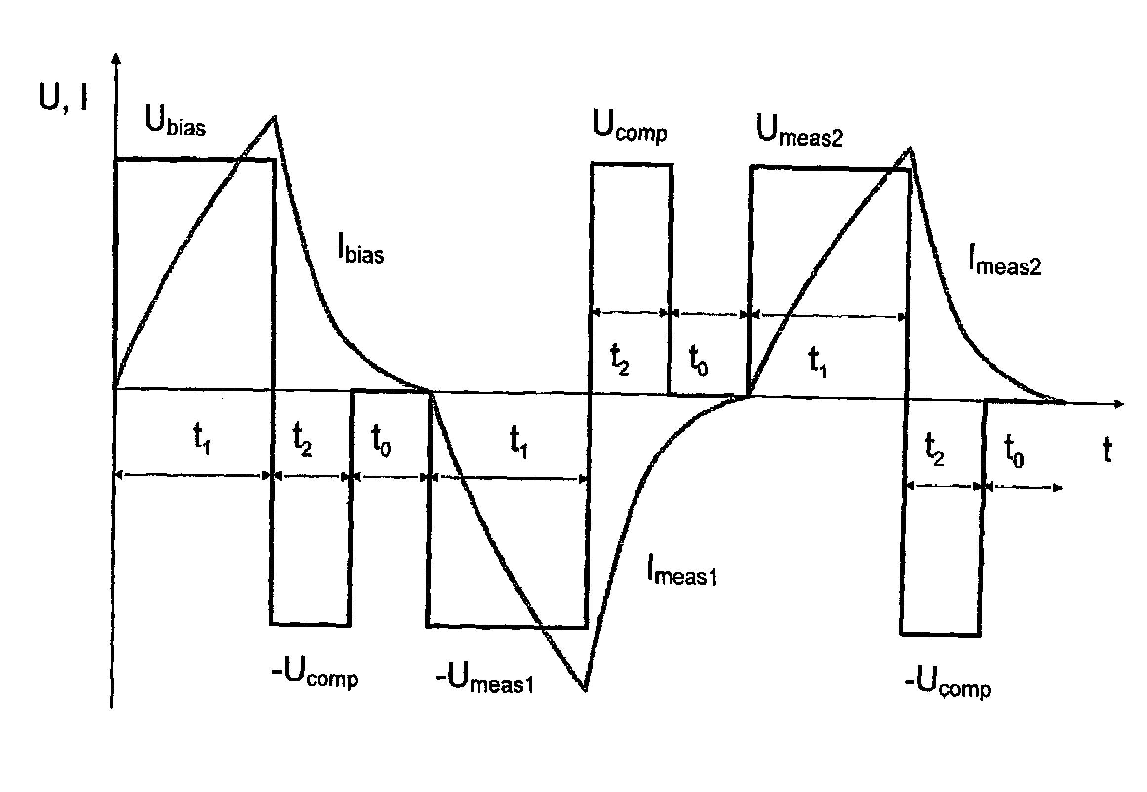
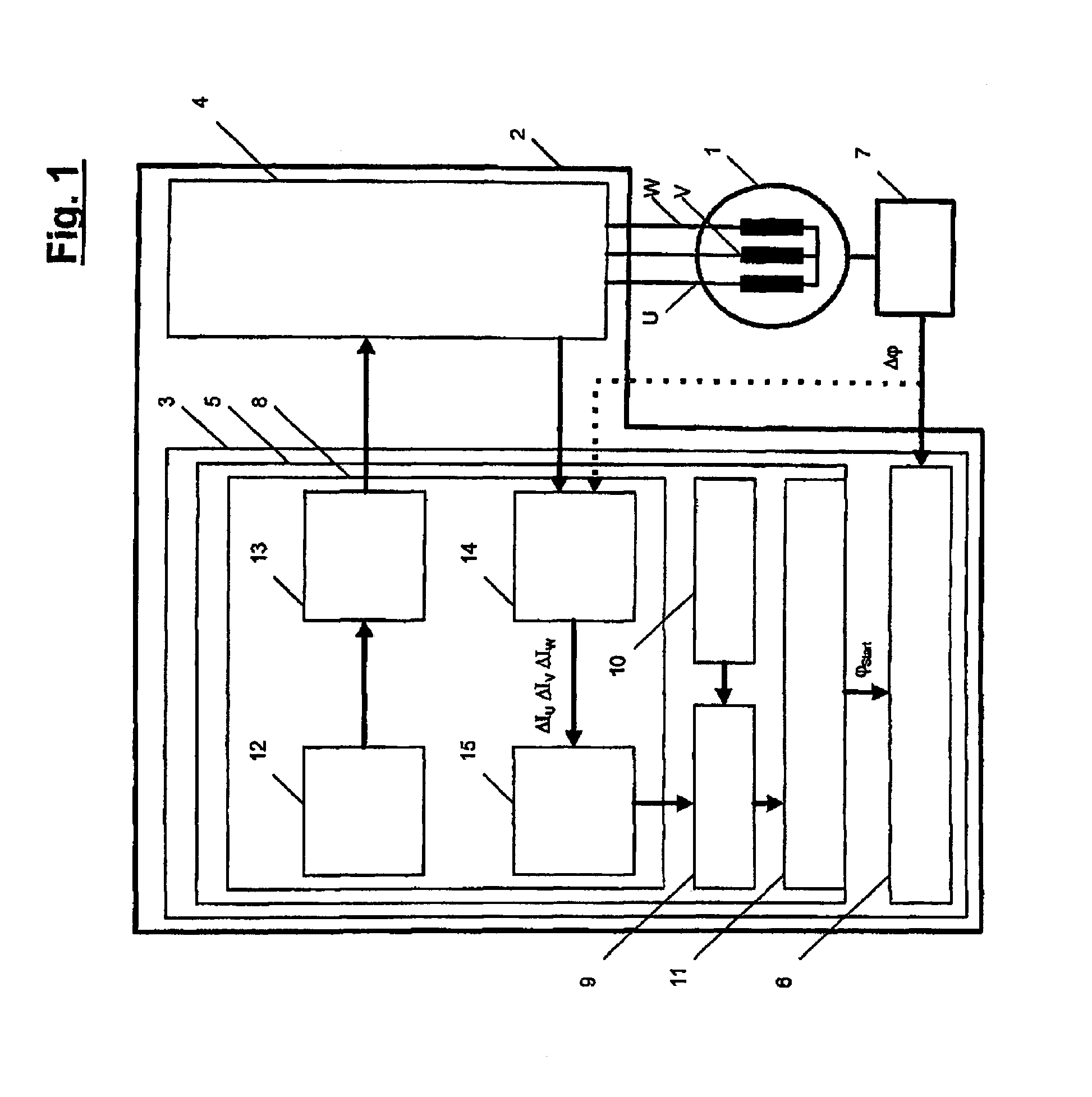
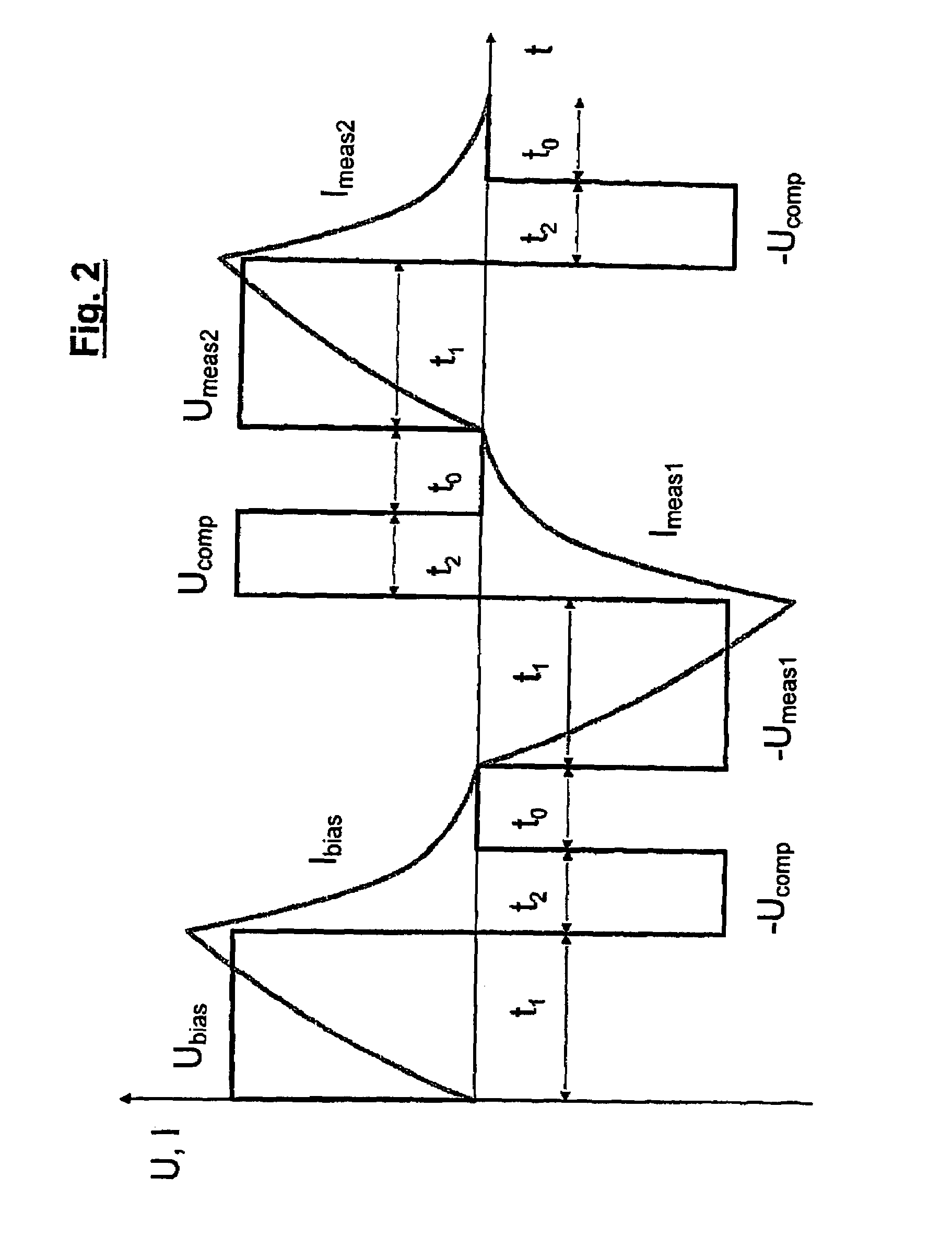
[0024]Referring to FIG. 1, reference numeral 1 designates a synchronous machine, and reference numeral 2 designates an actuation electronic unit associated with the synchronous machine 1. The actuation electronic unit 2 essentially comprises an actuation software module 3 and an output end stage 4, the output or voltage signals UU, UV and UW of which are applied to the phase windings U, V and W of the synchronous machine 1. The actuation software module 3 comprises a control module 5 for controlling the process of determining the rotor position of the synchronous machine 1 as well as a rotor position detection device 6 to which are sent output signals Δφ of a relative rotor position sensor 7, which reflect the change in the rotor position of the synchronous machine 1. The control module 5 comprises a test-value detection module 8, an evaluating module 9, a memory 10 in which a reference characteristic curve of the synchronous machine 1 is stored, ...


PUM


Abstract

The invention relates to a method for determining the rotor position of a stationary or slowly rotating synchronous machine by evaluating electrical test pulses that are obtained by applying voltage pulses to the individual phase windings of the stator, wherein changes in the inductance of the phase windings which are caused by saturation of the stator iron depending on the rotor position, are determined in opposite directions or current by calculating differences in the amount of current of two test pulses, and angle values being predetermined by the number of the phase windings are associated with the differences in the amount of current.
To enhance the measuring accuracy of the method, the invention provides that prior to the first test pulse Imeas1, a bias pulse Ibias whose polarity is inverted in relation to the first pulse Imeas1 is generated, with the switch-on times t1 of the associated voltage pulses Ubias and −Umeas1 being equal, and in that the respectively first test pulse Imeas1 generated in the corresponding phase winding (U, V, W) acts as a bias pulse in the same phase winding (U, V, W).

Description

BACKGROUND OF THE INVENTION[0001]The present invention relates to a method for determining the rotor position of a stationary or slowly rotating synchronous machine by evaluating electrical test pulses that are obtained by applying voltage pulses to the individual phase windings of the stator, wherein changes in the inductance of the phase windings which are caused by saturation of the stator iron depending on the rotor position, are determined in opposite directions of current by calculating differences in the amount of current of two test pulses, and angle values being predetermined by the number of the phase windings are associated with the differences in the amount of current.[0002]A method of this type is e.g. disclosed in U.S. Pat. No. 6,172,498 B1 being titled ‘Method and Apparatus for Rotor Angle Detection’. When the prior art method is implemented, test pulses of opposite polarity are applied to the individual phase windings of the stator, and difference values are produced...

Claims


Application Information

Patent Timeline
IPC IPC(8): G01B7/30G01D5/20H02P6/18
CPCG01D5/2006H02P6/185
Inventor STAUDER, PETERKAUFMANN, TOM
Owner CONTINENTAL TEVES AG & CO OHG
Why Eureka
Try Eureka