Temperature measuring method and apparatus

Inactive Publication Date: 2005-01-06
NORITAKE CO LTD +1
View PDF17 Cites 3 Cited by
  • Summary
  • Abstract
  • Description
  • Claims
  • Application Information

AI Technical Summary

Benefits of technology

[0010] The present invention has been developed in view of the findings discussed above. It is a first object of the present invention to provide a method which permits highly accurate measurement of a surface temperature of an object body in a furnace. A second object of the invention is to provide an apparatus suitable for practicing the method.

Problems solved by technology

Although this thermometer permits easy measurement of the temperature of the object body, it requires determination of the emissivity of the object body, and is not suitable for measuring temperature of an object body the emissivity of which changes.
The radiation thermometers of non-contact type capable of monochromatic or dichroic temperature measurement or other non-contact type radiation thermometers may suffer from insufficient accuracy of the temperature measurement of the object body, due to a stray light noise undesirably included in the light radiated from the object body.
Thus, the detected temperature of the object body is adversely influenced by the radiant energy of the stray light.
The degree of the adverse influence on the accuracy of measurement of the temperature of the object body increases with a rise in temperature of the inner wall surfaces of the furnace surrounding the object body, since the rise in the temperature of the surroundings causes an increase in the intensity of the radiant energy emitted from the inner wall surfaces of the furnace, as the stray light noise
However, where the temperature in the furnace is relatively high, the water-cooled shielding plate cools down the object body, leading to deterioration of the temperature measurement accuracy.
This apparatus suffers from a drawback that the measurement accuracy is not sufficiently high when the temperature distribution within the furnace wall is uneven, since the temperature of the furnace wall is detected by the radiation thermometer at only one local portion of the furnace wall.
Therefore, to employ a radiant energy emitted from one local portion of the entire wall surface as a radiant energy emitted from the furnace wall as a whole leads to deterioration in the accuracy of measuring the temperature of the object body.

Method used


Image

  • Temperature measuring method and apparatus
  • Temperature measuring method and apparatus
  • Temperature measuring method and apparatus

Examples


first embodiment

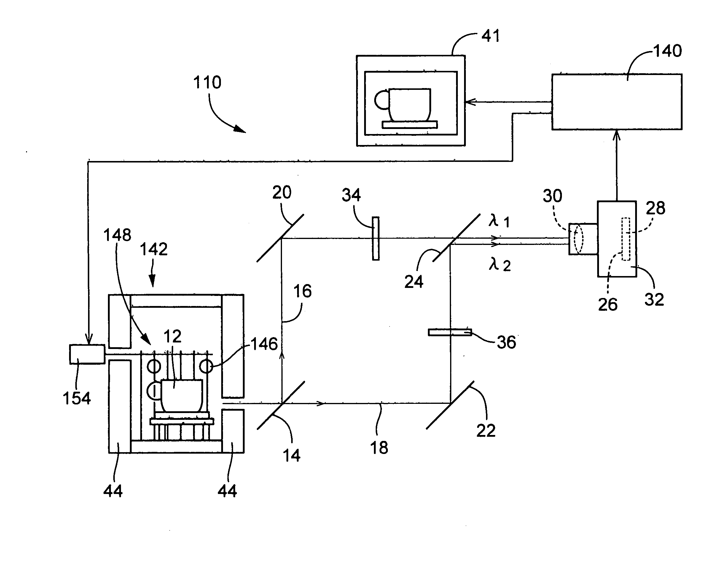
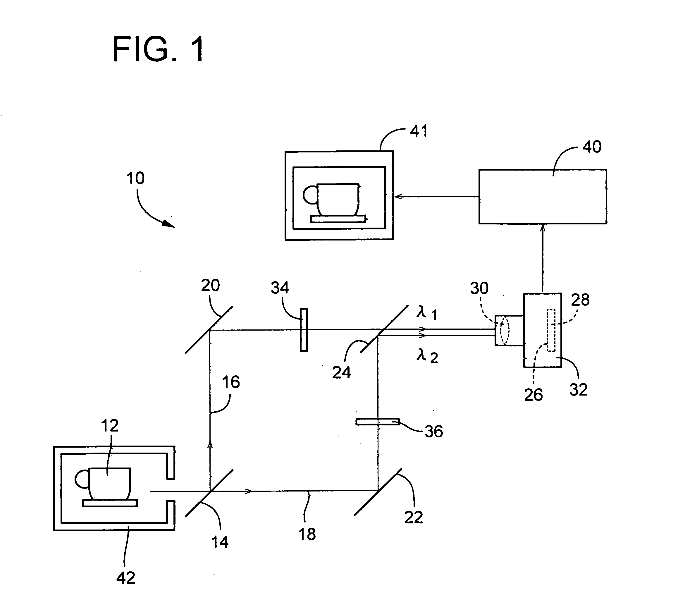
[0047] Referring first to FIG. 1, there is shown an arrangement of a temperature-distribution measuring apparatus 10 as this invention, wherein a light emitted or radiated from a surface of an object body 12 in a firing furnace or a heating furnace in the form of an electric furnace 42 is split by a half mirror (beam splitter) 14 into a first component traveling along a first optical path 16 and a second component traveling along a second optical path 18. The first and second optical paths 16, 18 are bent substantially at right angles by respective mirrors 20, 22, so that the first and second components are both incident upon a half mirror 24, and are reflected by the half mirror 24, so as to be incident upon an image detector 32 which has a CCD device 28 and a lens device 30. The CCD device 28 has a light detecting surface 26 on which are arranged a multiplicity of photosensitive elements. The lens device 30 is arranged to focus images of the object body 12 on the light detecting s...

second embodiment

[0078] As described above, the present invention is arranged such that: the object body 12 is heated in the heating step, while the shielding device disposed between the side furnace walls 44 of the heating furnace 142 and the object body 12 is in its open state; the intensity of the radiant energy emitted from the object body 12 is detected in step S12 corresponding to the radiant-energy detecting step or means, while the shielding device 148 is closed; and the temperature at each picture element of the image of the object body 12 is calculated in the step S15 corresponding to the temperature calculating step or means, based on the intensity of the radiant energy emitted from the object body 12 as detected in the step S12. Accordingly, the stray light noise or the intensity of the radiant energy of the stray light, which is emitted from the side furnace walls 44 and the burners 146 toward the object body 12 and reflected by the surface of the object body 12 and which is included in...


PUM


Abstract

A method of measuring a temperature of an object body in an electric furnace, based on an intensity of a radiant energy emitted from the object body, the electric furnace being provided with an electric heater operable by application of a drive voltage thereto to heat the object body, the method comprising: a radiant-energy detecting step of detecting an intensity of a radiant energy emitted from the object body; a stray-light noise eliminating step of determining as a noise an intensity of a radiant energy of a stray light which is emitted from an inner wall surface of the electric furnace toward the object body and reflected by a surface of the object body, according to a predetermined relationship between the intensity of the radiant energy of the stray light and the drive voltage applied to the electric heater and based on an actually applied value of the drive voltage, and subtracting the intensity of the radiant energy of the stray light determined as the noise, from the detected intensity of the radiant energy emitted from the object body; and a temperature calculating step of calculating a temperature of the object body, based on the intensity of the radiant energy emitted from the object body from which the noise has been removed in the stray-light noise eliminating step. Also disclosed is an apparatus for practicing the method, which may include a shielding device disposed between the furnace walls and the object body.

Description

[0001] This application is based on Japanese Patent Applications Nos. 2001-312962 and 2001-312963 both filed on Oct. 10, 2001, the contents of which are incorporated hereinto by reference. BACKGROUND OF THE INVENTION [0002] 1. Field of the Invention [0003] The present invention relates to a method and an apparatus which permit accurate measurement of temperature of an object body even in the case where the temperature of a wall such as a furnace wall surrounding the object body is different from that of the object body. [0004] 2. Discussion of Related Art [0005] Temperature measuring methods of non-contact type are industrially useful and widely employed. To practice such non-contact type temperature measuring methods, there are known a radiation thermometer operable to effect a monochromatic temperature measurement, and a radiation thermometer operable to effect a dichroic temperature measurement. The former thermometer measures the temperature of an object body by comparing a radi...

Claims


Application Information

Patent Timeline
IPC IPC(8): G01J5/00G01J5/60
CPCG01J5/0044G01J5/06G01J2005/0077G01J2005/0048G01J5/602G01J5/80
Inventor HASHIMOTO, MIYUKIYANO, KENJIIWATA, MISAOKITAGAWA, KUNIYUKIARAI, NORIOARAI, SATOSHI
Owner NORITAKE CO LTD
Why Eureka
Try Eureka