Procedure to minimize the risk of air collision for personal mid-air vehicles

a technology of air collision and vehicle, applied in the field of flight control method and system, can solve the problems of high construction and maintenance costs high cost of current roads and freeways, and high traffic congestion of roads and freeways, so as to reduce the risk of mid-air collisions

a technology of air collision and vehicle, applied in the field of flight control method and system, can solve the problems of high construction and maintenance costs high cost of current roads and freeways, and high traffic congestion of roads and freeways, so as to reduce the risk of mid-air collisions

US7389163B1Active Publication Date: 2008-06-17THE BOEING CO

Image

  • Procedure to minimize the risk of air collision for personal mid-air vehicles
  • Procedure to minimize the risk of air collision for personal mid-air vehicles
  • Procedure to minimize the risk of air collision for personal mid-air vehicles

Examples


Embodiment Construction

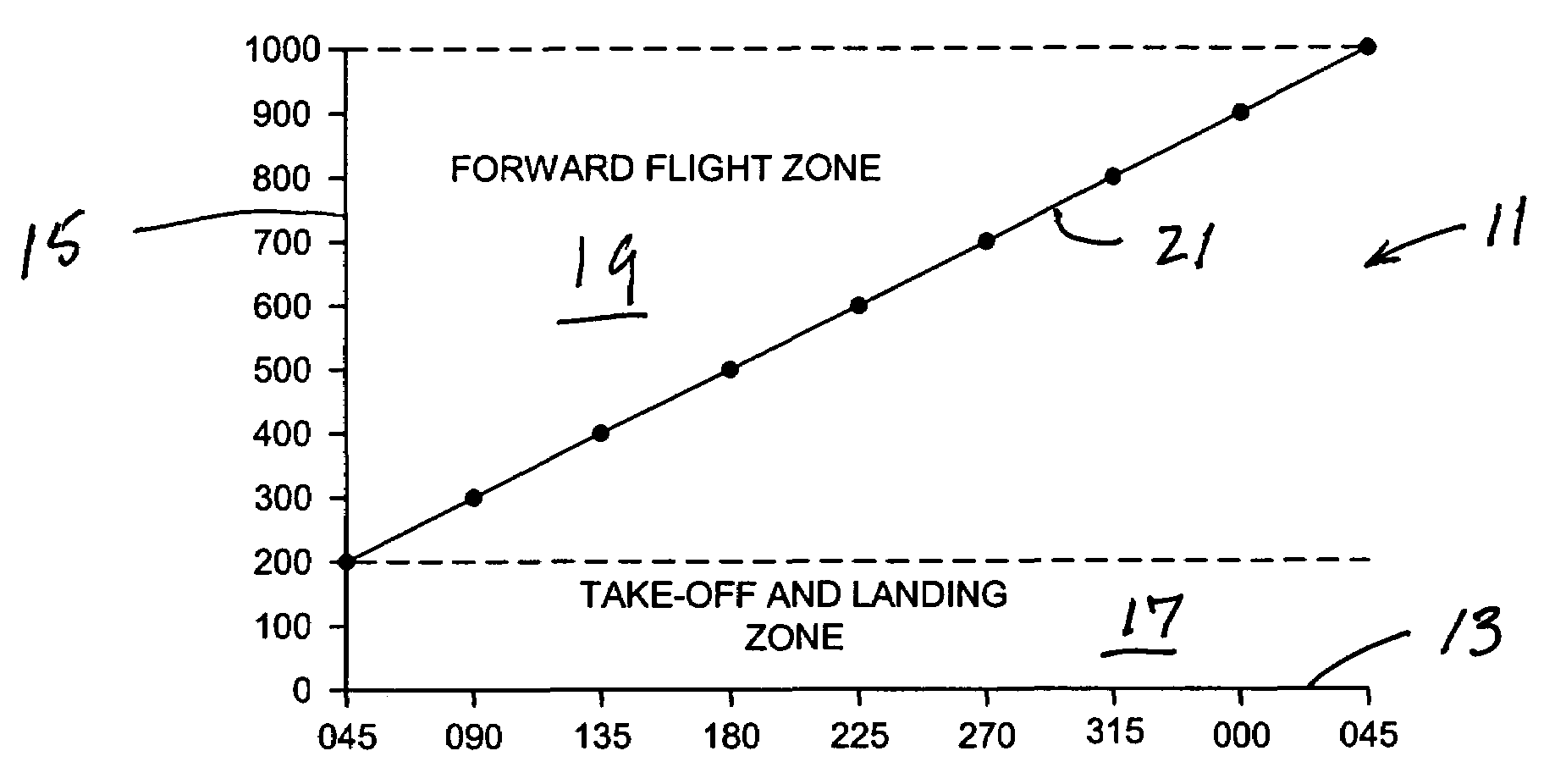
[0025]Referring now to the drawings, and first to FIG. 1, a graphical representation of features of an embodiment of the present invention is designated generally by the numeral 11. Graphical representation 11 includes a heading axis 13 and an altitude axis 15. The units in heading axis 13 are degrees magnetic, although the units could be degrees true. The heading for the origin is selected to be 045° magnetic, although other headings could be used at the origin. The units of altitude axis 15 are feet above the ground. At the origin, the altitude is 0, or the surface of the ground.

[0026]Graphical representation is divided into a take-off-and-landing zone 17 and a forward flight zone 19. Take-off-and-landing zone 17 extends from the surface of the ground to an altitude of 200 feet above the surface of the ground. Forward flight zone 19 extends from an altitude of 200 feet above the ground to an altitude of 1000 feet above the ground. In the embodiment of FIG. 1, 1000 feet above the g...


PUM


Abstract

A method of and a system for controlling personal air vehicle (PAV) traffic provides a take-off-and-landing zone, and a forward flight zone. The take-off-and-landing zone may be from the ground up to a first altitude. The forward flight zone may be from the first altitude up to a second altitude. A maximum airspeed is provided in the take-off-and-landing zone. Minimum and maximum airspeeds are provided in the forward flight zone. In the forward flight zone there is a single heading for each altitude. Any change in heading must be accompanied by a change in altitude.

Description

BACKGROUND OF THE INVENTION[0001]The present invention provides a flight control method and system, and more particularly a method of and system for minimizing the risk of mid-air collisions between personal air vehicles.[0002]Currently, particularly in areas of the country where the majority of people are unable or unwilling to use public transportation, the automobile is the mode of choice for personal point-to-point transportation. Every day, millions of people in urban areas use automobiles to commute to and from work. Typically, a commute involves driving on surface streets and roads from home to a freeway system, driving on the freeway system to an off-ramp near a destination, and driving on surface streets or roads to the destination.[0003]The current system of roads and freeways is expensive. Roads and freeways are expensive to build and maintain. With the growth of population and the economy, more people use the existing road and freeway systems every year. Roads and freewa...

Claims


Application Information

Patent Timeline
17 Jun 2008
Publication
US7389163B1
IPC
G05D1/04; G08G5/04; G08G7/02
CPC
G08G5/006; G08G5/0065; G08G5/025
Inventors
COLICH, JOSEPH M.