Electric mail system

a technology of electronic mail and electronic mail, applied in the field of electronic mail (email) system, can solve the problems of reducing the efficiency of utilizing the e-mail system, increasing the load on the operations of users, etc., and achieve the effect of reducing the waste of resources, ensuring privacy, and thereby maximizing the utilization of the e-mail system

Inactive Publication Date: 2008-06-17
FUJITSU LTD
View PDF28 Cites 22 Cited by
  • Summary
  • Abstract
  • Description
  • Claims
  • Application Information

AI Technical Summary

Benefits of technology

[0010]Accordingly, it is a primary object of the present invention to provide an E-mail terminal device and a readable-by-computer medium recorded with a program which are capable of preventing a reply mail from being mis-transmitted to a mailing list.
[0011]It is another object of the present invention to provide a technology of enhancing an efficiency of utilizing an E-mail system by reducing a load upon operations of the users.
[0030]According to the present invention, it is feasible to prevent the reply mail from being mis-transmitted to the mailing list.
[0031]As a result, it is possible to prevent such a mistake that the mail having a private content is broadcast to all the members, whereby the privacy can be protected. Further, with a reduction of mis-transmitted E-mails, a futile consumption of resources can be decreased.
[0032]Moreover, according to the present invention, the user is cable to simply designate the mail address of the reply destination (the mail address of the addressee), and the E-mail system can be thereby utilized efficiently.

Problems solved by technology

While on the other hand, there might occur an endless chain of mistakes in which the reply mail is mis-transmitted to the address of the mailing list with an intention that the reply mail would have been given to the individual information transmitter having posted to the mailing list, and it follows that the private reply mail is broadcast to all the registered members.
Accordingly, the users are required to confirm the addressee when creating and transmitting the reply mail and designate to a correct address of the addressee, which might lead an increase in load upon the operations of the users and cause a decrease in an efficiency of utilizing the E-mail system.

Method used


Image

  • Electric mail system
  • Electric mail system
  • Electric mail system

Examples


Embodiment Construction

[0042]Next, embodiments of the present invention will hereinafter be described with reference to the accompanying drawings.

[Architecture of E-mail System]

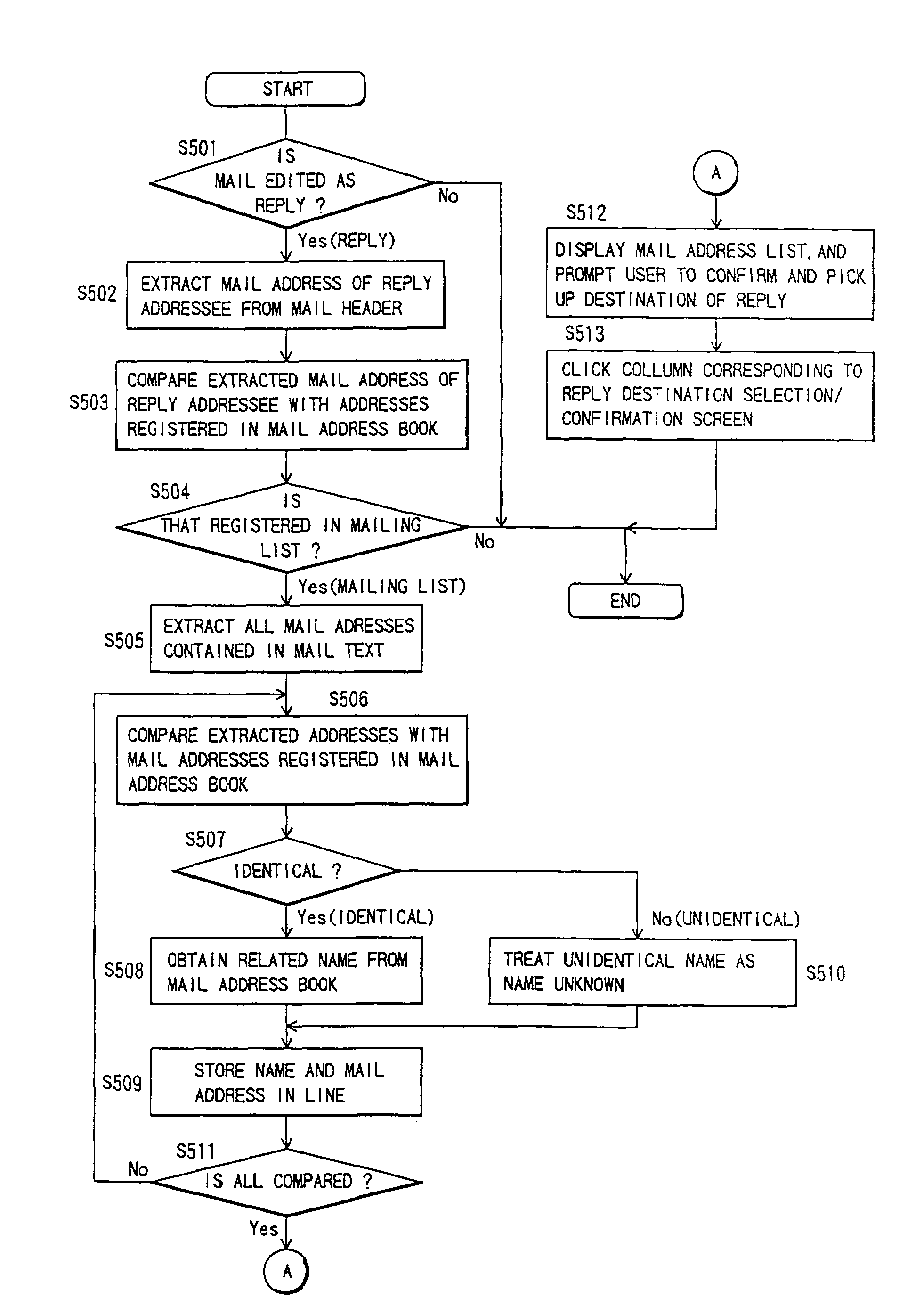
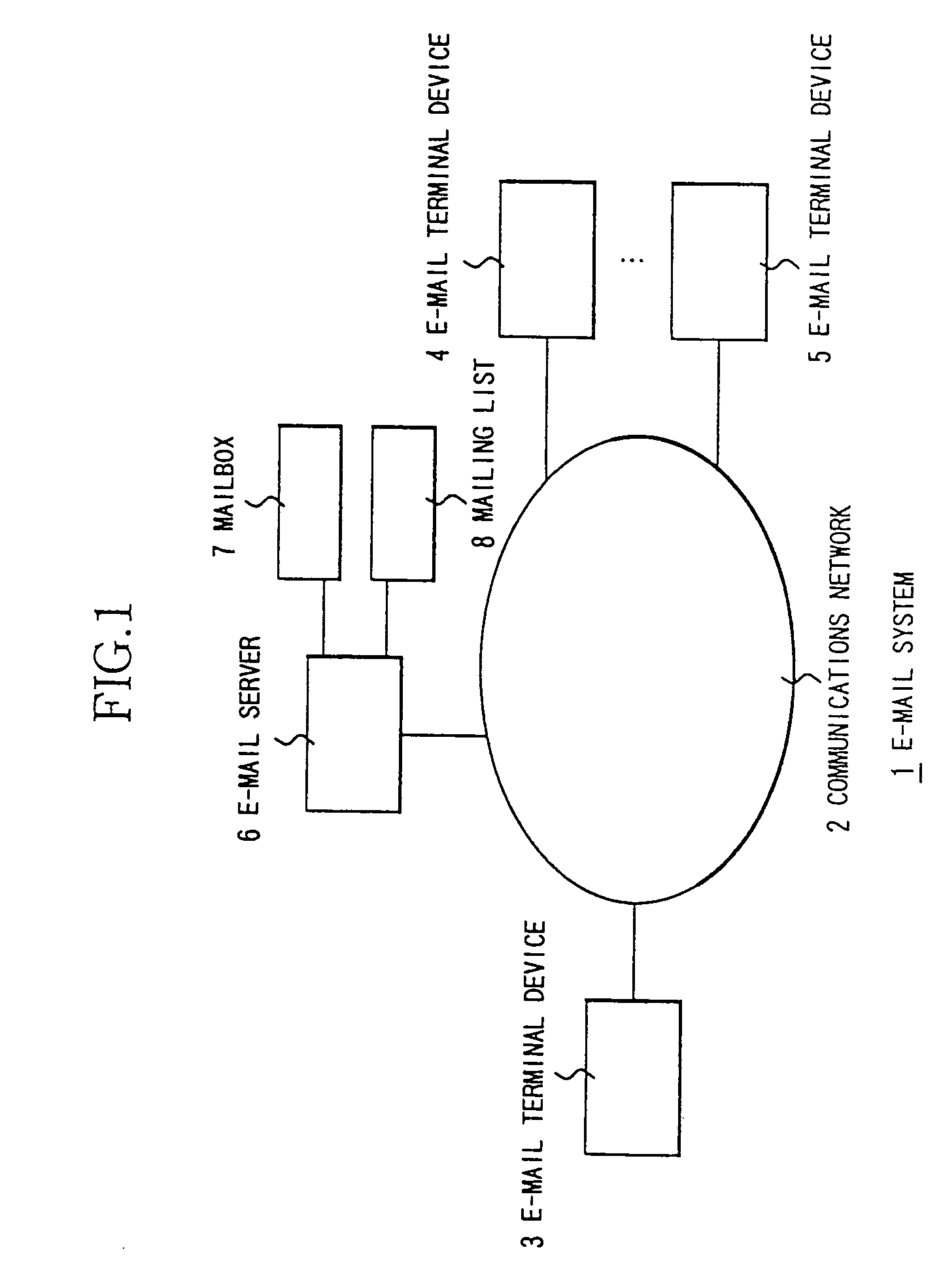
[0043]FIG. 1 shows an architecture of an E-mail system in one embodiment of the present invention. Referring to FIG. 1, the E-mail system 1 includes a plurality of E-mail terminal devices 3, 4, . . . , 5 each accommodated in a communications network 2, and an E-mail server (an E-mail post) 6. The communications network 2 is constructed of the Internet and an intraoffice local a real network (LAN).

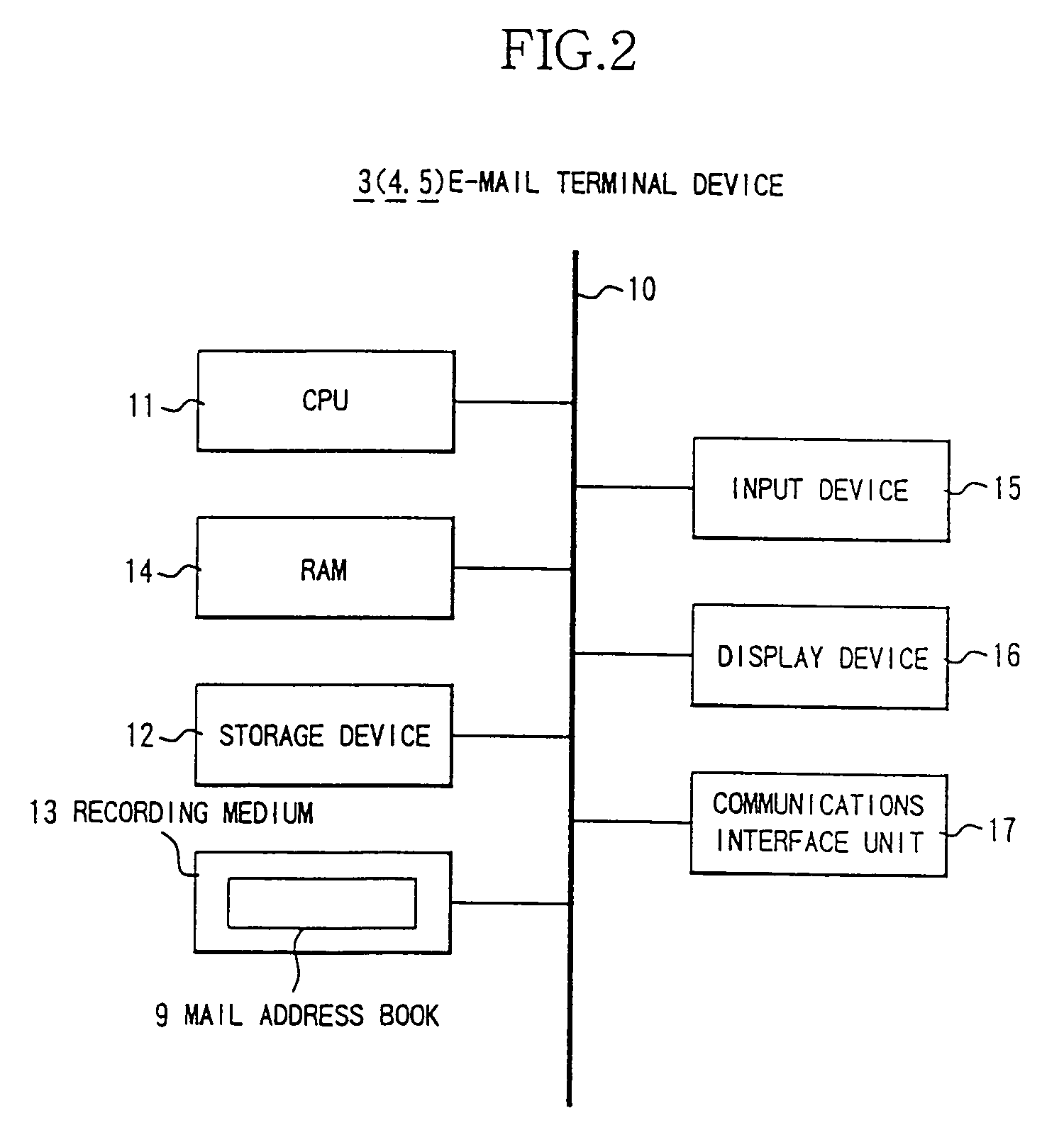
[0044]The E-mail terminal devices 3, 4, . . . , 5 are constructed of computer terminals such as personal computers (PCs) or data terminals such as workstations (WSs). E-mail addresses, which are each unique, are allocated to the respective E-mail terminal devices. Further, each of the E-mail terminal devices has a mail address book. Each of the E-mail terminal devices incorporates E-mail software (programs and data), and transmits and rece...


PUM


Abstract

An E-mail terminal device comprises a judging unit which judges whether or not a reply destination mail address extracted from an E-mail received is an address of a mailing list capable of broadcasting the same E-mail to a plurality of destinations at one time, an extracting unit which extracts, when the reply destination mail address is the address of the mailing list, at least one mail address contained in a text of the E-mail received, and a selecting module which displays the at least one extracted mail address as a candidate for a reply destination from which a specified reply destination can be selected. This construction makes it feasible to prevent a reply mail from being mis-transmitted to the mailing list.

Description

BACKGROUND OF THE INVENTION[0001]The present invention relates generally to an electronic mail (E-mail) system, and more particularly to an E-mail terminal device, an E-mail transmitting method and a readable-by-computer medium recorded with a program which are capable of preventing an E-mail from being mis-replied (mis-transmitted).[0002]E-mail services have spread most as applications and services in the communication networks over the recent years.[0003]The E-mail system is defined as a technology of transmitting and receiving mail data (including character information, voice information and picture information) between E-mail terminal devices connected to communications networks, i.e., between computer terminals such as personal computers (PCs) and between data terminals such as workstations (WSs).[0004]In the E-mail system for exchanging the mail data by way of the E-mails, a transmission of the E-mail from a certain E-mail terminal device to other E-mail terminal device involv...

Claims


Application Information

Patent Timeline
Patent Type & Authority Patents(United States)
IPC IPC(8): G06F15/16G06F13/00H04L12/18H04L12/58
CPCH04L12/58H04L51/48
Inventor MIYAZAWA, YOSHINORI
Owner FUJITSU LTD
Why Eureka
Try Eureka