Nailer with a safety device

a safety device and nailer technology, applied in the direction of nailing tools, nailing tools, stapling tools, etc., can solve the problems of inconvenient nailing operation, excessively long nailing time, and the risk of fatal accidents of the nailing machin

Inactive Publication Date: 2008-06-24
JEIL TACKER
View PDF16 Cites 12 Cited by
  • Summary
  • Abstract
  • Description
  • Claims
  • Application Information

AI Technical Summary

Benefits of technology

[0026]Therefore, the present invention has been made in view of the above problems, and it is an object of the present invention to provide a nailer having an improved safety device wherein a movable plate, which is adapted to slidably move along a lower surface of a guiding unit, is formed, at a certain location thereof, with an insertion hole for the insertion of a protrusion formed at a trigger, so as to be moved rearward by a predetermined distance under interaction of the insertion hole and protrusion while allowing implementation of a nailing operation when the trigger is pulled in a pressed state of the movable plate, thereby eliminating the risk of causing scratches on a nailing surface of a target structure even if the movable plate is moved while coming into close contact, at a front end thereof, with the nailing surface and consequently, resulting in several advantages, such as for example, easy nailing operation, operator's convenient working posture, and rapid and safe nailing operation.
[0030]Preferably, the control protrusion may be configured to protrude forward from the trigger body by a predetermined angle, whereby, if the trigger is fully pulled after the control protrusion of the trigger is inserted into the insertion hole perforated in the movable plate, the control protrusion causes the movable plate to be further pulled toward the handle by a predetermined distance, thereby preventing the contact portion of the safety device from causing scratches on the nailing surface even if the nailer is moved in a state wherein a front end of the guiding unit included in the nailer comes into close contact with the nailing surface.

Problems solved by technology

When using the above described conventional nailing machine 2, however, it should be noted that the nailing machine 2 has the risk of fatal accidents if long or large projectile objects including tacks, nails, etc. are launched to unwanted target structures by unintentional trigger pulling manipulation.
Meanwhile, it is noted that the above described safety devices have not been used in most small-scale nailing machines.
When using the above described safety device, however, since the trigger 13 can be pulled to accomplish a nailing operation only after the movable plate 18 is pressed by the target structure, the conventional nailing machine 2 has problems of inconvenient nailing operation and excessively long nailing time.
Furthermore, if the movable plate 18 is moved in a state wherein a front end thereof is pressed by the target structure, there is the risk of imparting scratches to the target structure.
However, the above described conventional nailing machine 22 also has a problem in that it may cause scratches on the target structure if the movable plate 24 is moved in a state wherein the front end thereof is pressed by the target structure.
When using the auxiliary trigger 32, however, since the operator has to pull the trigger 13 with the first finger in a state of pulling the auxiliary trigger 32 with the second finger, it can be said that the auxiliary trigger 32 actually has less safety effect and has a high risk of causing an unintentional nailing operation.
Accordingly, the nailing machine 30 using the auxiliary trigger 32 as a safety device suffers from a rate of accidents.

Method used


Image

  • Nailer with a safety device
  • Nailer with a safety device
  • Nailer with a safety device

Examples


first embodiment

[0045]Referring to the drawings, the nailer 40 having an improved safety device according to the present invention has a feature in that a movable plate, which is adapted to slidably move along a lower surface of a guiding unit, is perforated, at a predetermined portion thereof, with an insertion hole for the insertion of a protrusion formed at a trigger, so as to be moved rearward by a predetermined distance under interaction of the insertion hole and protrusion while allowing implementation of a nailing operation when the trigger is pulled in a pressed state of the movable plate, thereby eliminating the risk of causing scratches on a nailing surface of a target structure even if the movable plate is moved while coming into close contact, at a front end thereof, with the nailing surface, resulting in several advantages, such as for example, easy nailing operation, operator's convenient working posture, and rapid and safe nailing operation.

[0046]For this, the nailer 40 having an imp...

second embodiment

[0060]Now, the present invention will be explained in detail with reference to the accompanying drawings.

[0061]FIGS. 8A, 8B, and 8C are partial side sectional views illustrating the operation of important parts of a nailer having an improved safety device according to the second embodiment of the present invention.

[0062]Referring to the drawings, the nailer having the improved safety device according to the second embodiment of the present invention has approximately the same configuration as that of the first embodiment, and repeated description related to the same reference numerals will be omitted.

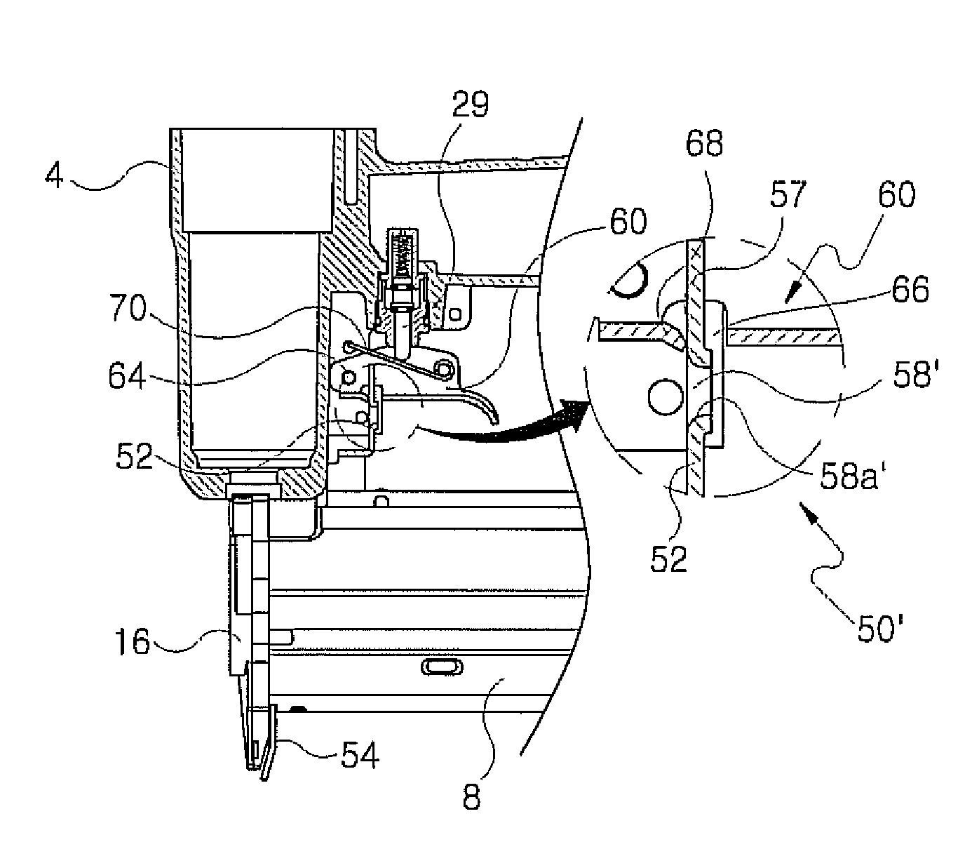
[0063]The nailer having the improved safety device according to the second embodiment of the present invention has a feature in that an insertion hole 58′ of the movable plate 52, into which the control protrusion 68 formed at the upper end of the inner periphery of the insertion hole 66 formed in the trigger 60 is inserted, has a rounded inner periphery 58′.

[0064]If the trigger 60 is p...

third embodiment

[0065]Now, the present invention will be explained in detail with reference to the accompanying drawings.

[0066]FIGS. 9A, 9B, and 9C are partial side sectional views illustrating the operation of important parts provided in a nailer having an improved safety device according to the third embodiment of the present invention.

[0067]In the case of the previously described nailers having the improved safety devices according to the first and second embodiments of the present invention, they perform no nailing operation in a state wherein the movable plate 52 is not moved toward the handle 12 because the movable plate 52 acts to prevent the trigger 60 from being pulled. Also, even when the movable plate 52 of the safety device is pressed toward the handle 12 in the course of pulling the trigger 60, the control protrusion 68 of the trigger 60 comes into contact with the retardant portion 57 formed at the rear end of the movable plate 52, thereby acting to prevent the trigger 60 from being r...


PUM

PropertyMeasurementUnit
moving distanceaaaaaaaaaa
distanceaaaaaaaaaa
sizeaaaaaaaaaa

Abstract

Disclosed herein is a nailer having an improved safety device. With the improved safety device, a movable plate, which is adapted to slidably move along a lower surface of a guiding unit, is formed, at a certain location thereof, with an insertion hole for the insertion of a protrusion formed at a trigger. Thereby, if the trigger is pulled in a pressed state of the movable plate, a nailing operation is accomplished. Also, in the course of pulling the trigger, the movable plate can be further inserted rearward by a predetermined distance under interaction of the insertion hole and protrusion. This has the effect of eliminating the risk of causing scratches on a nailing surface of a target structure even if the movable plate is moved while coming into close contact, at a front end thereof, with the nailing surface, resulting in several advantages, such as for example, easy nailing operation, operator's convenient working posture, and rapid and safe nailing operation.

Description

[0001]This application is based on and claims priority to Korean Patent Application No. 10-2006-0091583 filed on Sep. 21, 2006 in the Korean Intellectual Property Office (KIPO), the entire contents of which are hereby incorporated by reference.BACKGROUND OF THE INVENTION[0002]1. Field of the Invention[0003]The present invention relates to a nailer having an improved safety device, and, more particularly, to a nailer having an improved safety device wherein a movable plate, which is adapted to slidably move along a lower surface of a guiding unit, is formed, at a certain location thereof, with an insertion hole for the insertion of a protrusion formed at a trigger, so as to be moved rearward by a predetermined distance under interaction of the insertion hole and protrusion while allowing implementation of a nailing operation when the trigger is pulled in a pressed state of the movable plate, thereby eliminating the risk of causing scratches on a nailing surface of a target structure ...

Claims


Application Information

Patent Timeline
Patent Type & Authority Patents(United States)
IPC IPC(8): B25C1/04
CPCB25C1/008B25C1/043B25C1/04B25D9/00B25D17/00
Inventor CHO, BO-SEOBHAN, JONG-YEOLKIM, JIN-WON
Owner JEIL TACKER
Why Eureka
Try Eureka