Semiconductor radiation detector with guard ring, and imaging system with this detector

a technology of electromagnetic radiation detector and guard ring, which is applied in the field of electromagnetic/xray imaging system, can solve the problems of difficult realization of guard ring at the end portions of each x-ray detecting region, inability to read signals from x-ray detecting elements in the x-ray detecting region separately, and inability to obtain signals incident between the x-ray detecting elements, etc., to achieve the effect of reducing noise, expanding dynamic range and increasing snr

Inactive Publication Date: 2008-06-24
HITACHI LTD
View PDF11 Cites 11 Cited by
  • Summary
  • Abstract
  • Description
  • Claims
  • Application Information

AI Technical Summary

Benefits of technology

[0017]When the X-ray CT scanner is used, as disclosed in Patent Document 2, there are cases in which imaging is conducted by changing the slice thickness with which reconstruction is conducted or the slice width with which imaging with X-ray irradiation is conducted. Regarding such change in slice thickness, there is a reconstruction method in which signals from X-ray detecting elements adjacent in the slice direction are subjected to weighted summation (to be hereafter referred to as “binning”) depending on imaging conditions, and the signals are virtually considered to be a signal from one element. There are cases in which such addition is conducted on analog signals and cases in which it is conducted on digital signals. Such processing is advantageous in that reconstructed images having less noise can be obtained, the volume of data can be compressed, and transfer / processing time can be reduced, for example.

Problems solved by technology

However, when there is a guard-ring structure, such as a guard-ring electrode or a groove between the X-ray detecting elements, it is problematic in that signals incident between the X-ray detecting elements cannot be obtained.
However, based on conventional technology, it is difficult to realize such guard-ring at the end portions of each X-ray detecting region.
However, in the case of an X-ray detector of a sequential readout system, since a common readout circuit is connected, in order to apply a voltage to the X-ray detecting elements in ineffective regions, switches need to be turned on, and thus signals from the X-ray detecting elements in the X-ray detecting region cannot be separately read.
Thus, the X-ray detecting elements in the ineffective regions cannot be used as guard-ring electrodes.
Thus, in the case of a detector of a sequential readout system, when the slice width with which imaging is conducted is changed, it is problematic in that the electrodes of the X-ray detecting elements in the ineffective regions cannot be used as guard-ring electrodes.

Method used


Image

  • Semiconductor radiation detector with guard ring, and imaging system with this detector
  • Semiconductor radiation detector with guard ring, and imaging system with this detector
  • Semiconductor radiation detector with guard ring, and imaging system with this detector

Examples


embodiment 1

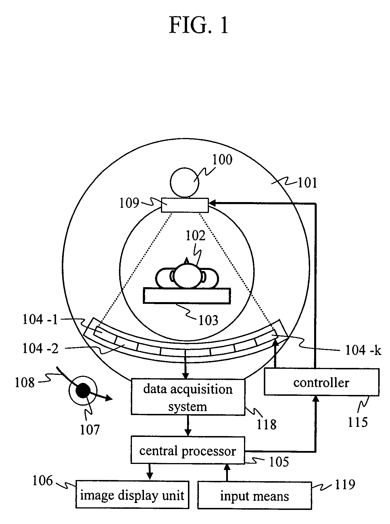
[0053]The present embodiment relates to a medical X-ray CT scanner, which is an object to which the present invention is applied, and in the present embodiment, the position or the presence / absence of a guard-ring can be changed in accordance with conditions of the imaging field of view (FOV). Embodiment 1 of the present invention will be described hereafter with reference to FIGS. 1 to 11.

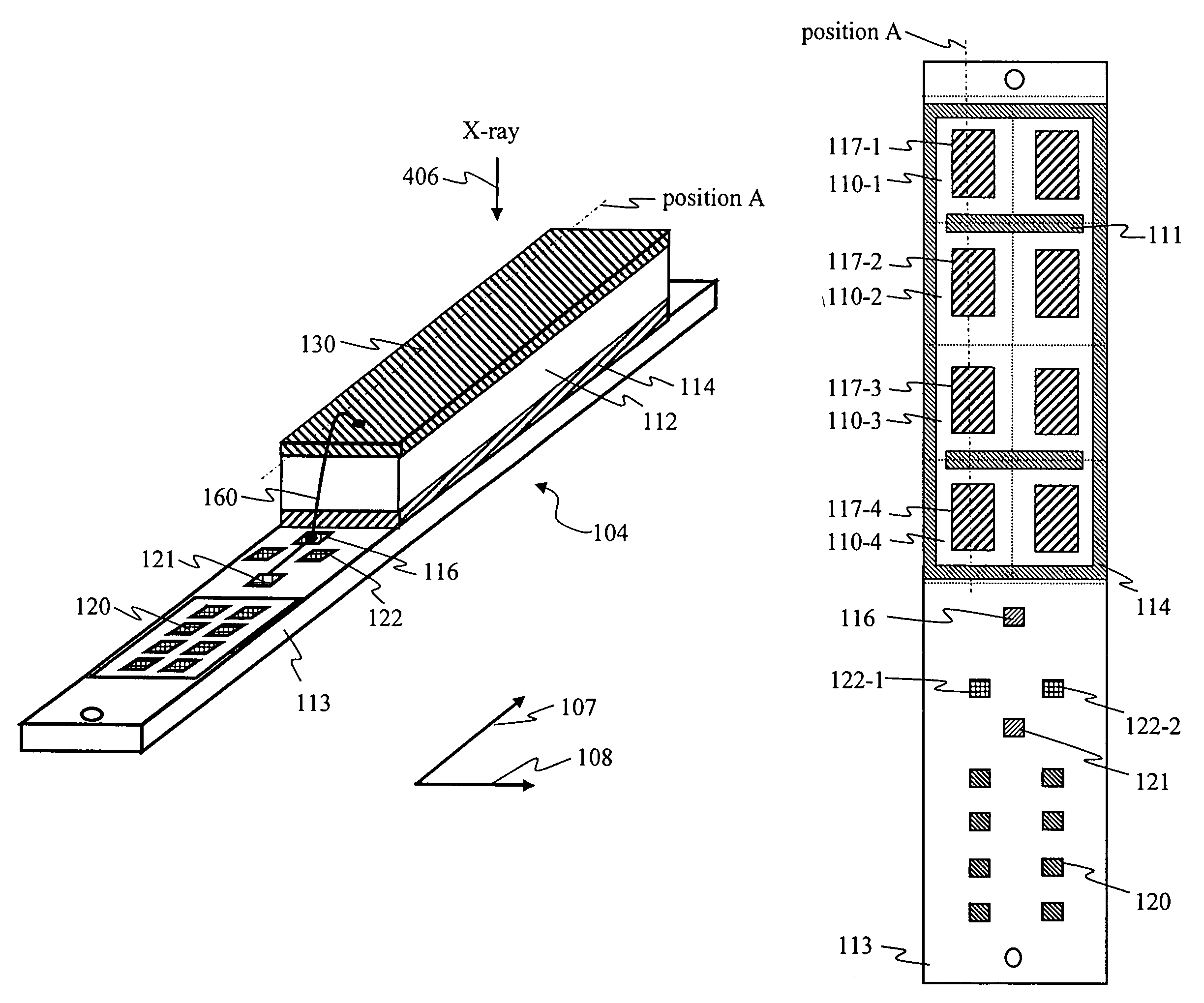
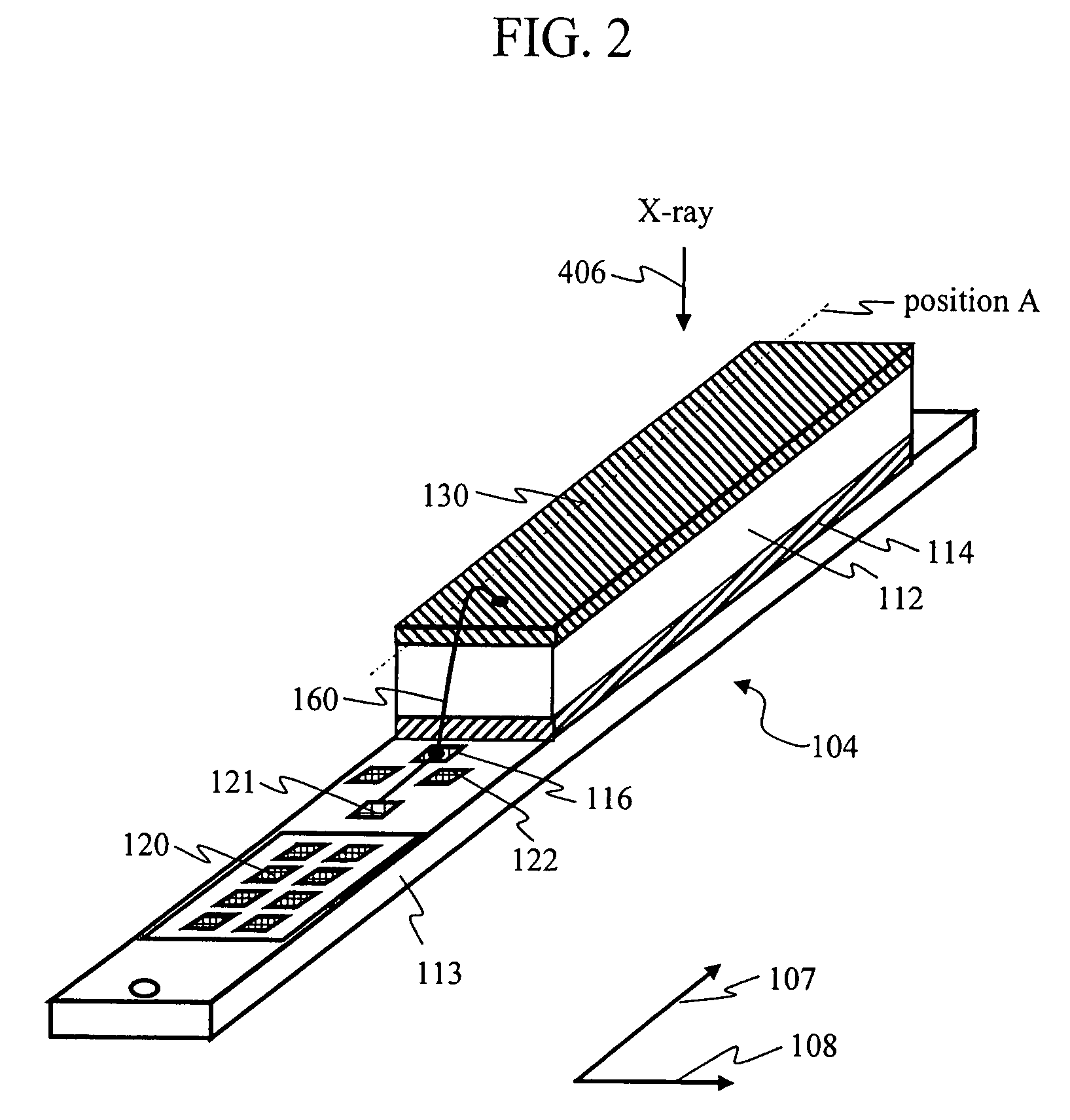
[0054]FIG. 1 schematically shows an X-ray CT scanner of the present embodiment. FIG. 2 is an example of an X-ray detector mounted on the X-ray CT scanner of FIG. 1. FIG. 3 shows the configuration of pixel electrodes and guard-ring electrodes formed on a distribution module 113. FIGS. 4 and 5 show an example of electric lines of the pixel electrodes and an example of electric lines of the guard-ring electrodes, respectively. FIGS. 6 and 7 show cross-sectional views taken along position A of FIGS. 2 and 3, and the figures show the difference in electric field, depending on the presence or absence of...

embodiment 2

[0075]An X-ray CT scanner of the present embodiment is the same as that described with FIG. 1 in Embodiment 1, and the structure of the X-ray detector 104 is also the same as that described with FIG. 2 in Embodiment 1. FIG. 12 shows an example of the configuration of the guard-ring electrodes of the X-ray detector 104 according to the present embodiment. FIG. 13 shows an example of electric lines of the guard-ring electrodes of FIG. 12. The X-ray CT scanner of the present embodiment comprises a function (binning) of adding signals from adjacent X-ray detecting elements and is capable of changing the position or the presence / absence of the guard rings, depending on binning conditions. FIG. 14 and FIG. 15 show cross-sectional views explaining the appearance of electric fields when the binning is present and absent.

[0076]Hereafter, as one example of imaging conditions involving different kinds of binning, no-binning imaging in which binning is not conducted, and two-pixel binning imagi...

embodiment 3

[0086]An X-ray CT scanner of the present embodiment is the same as that shown in FIG. 1 described in Embodiment 1. Based on the X-ray CT scanner in Embodiment 2, while the interelement guard-ring electrodes 111 are not connected to the readout circuit, in the present embodiment, the interelement guard-ring electrodes 111 can be connected to the readout circuit, and switching between the connection to ground potential and the connection to the readout circuit is made possible, depending on binning conditions.

[0087]Based on the X-ray CT scanner of the present embodiment, when the binning is not conducted, the interelement guard-ring electrodes 111 are connected to ground potential. In contrast, when the binning is conducted, the interelement guard-ring electrodes 111 are connected to the readout circuit in the data acquisition system 118. FIG. 18 shows an example of the processing of the data acquisition system 118 in such case. As shown in FIG. 18, the output signals from the pixel e...


PUM


Abstract

A guard-ring electrode can be used at a suitable position for each of a plurality of imaging regions. Improvement in image quality and reduction in unnecessary radiation exposure, such as reduction in artifacts or noise, improvement in SNR, and expansion in dynamic range, are realized by reducing the cross-talk or the inflow of electrical charges from ineffective regions. Based on a radiation detector having a plurality of pixel electrodes 117 and a common electrode that sandwich a photoelectric conversion layer, an interelement guard-ring electrode 111 is adjacently disposed between the pixel electrodes 117 of the radiation detecting element, and the interelement guard-ring electrode 111 is switched between an electrically open-circuit state and a ground-potential connection state, so as to change the area in which the radiation detecting element detects radiation.

Description

CLAIM OF PRIORITY[0001]The present application claims priority from Japanese application JP 2006-149524 filed on May 30, 2006, the content of which is hereby incorporated by reference into this application.BACKGROUND OF THE INVENTION[0002]1. Field of the Invention[0003]The present invention relates to radiation / X-ray imaging systems, such as medical X-ray / radiation imaging systems, X-ray inspection systems, X-ray analysis systems, and radiation monitoring systems, and to semiconductor radiation detectors used in these systems.[0004]2. Background Art[0005]Cases in which an X-ray detector, which is one example of a semiconductor radiation detector, is applied to a multi-slice X-ray CT scanner will be hereafter described as a representative example. An X-ray CT scanner is an apparatus with which imaging is conducted on an object in a plurality of directions, and it calculates X-ray attenuation coefficients based on the projection, so as to obtain cross-sectional views of the object. Su...

Claims


Application Information

Patent Timeline
Patent Type & Authority Patents(United States)
IPC IPC(8): H05G1/64
CPCA61B6/032G01T1/249G01T1/241
Inventor KONNO, YASUTAKA
Owner HITACHI LTD
Why Eureka
Try Eureka