Image processing method

a processing method and image technology, applied in the field of image processing, can solve the problems of not being able the image of saved digital documents gradually deteriorating, and the inability to search for a saved file based on printed documents, so as to minimize the deterioration of images and minimize the required storage capacity

Inactive Publication Date: 2008-06-24
CANON KK
View PDF18 Cites 55 Cited by
  • Summary
  • Abstract
  • Description
  • Claims
  • Application Information

AI Technical Summary

Benefits of technology

[0011]The present invention has been made in consideration of these problems, and has as its object to provide an image processing method, image processing apparatus, and the like, which can minimize deterioration of an image without losing any information on a paper document, and can minimize a required storage capacity.

Problems solved by technology

However, this technique cannot search for a saved file based on the printed document.
Hence, when print and scan processes are repeated, the saved digital document image gradually deteriorates.
However, this technique cannot search for a saved file based on the printed document, and it is difficult to re-use the saved document.
Furthermore, during conversion into a PDF file, other processes cannot be done.
Hence, upon generating a document using the stored contents, the user must determine contents to be used, thus taking a lot of trouble.
However, since the difference information directly handles a scanned image, a large storage capacity is required.
However, when the PDL command is merely appended to the scanned image to convert that image into the PDL format, a relatively large file size is required.
Also, in case of a document file having no pointer information to an original data file, an original data file cannot be searched for.

Method used


Image

  • Image processing method
  • Image processing method
  • Image processing method

Examples


first embodiment

(Variation Applicable to First Embodiment)

[0188]In the above description, the extracted difference information is composited to the original digital file to form a new digital file, and the new digital file is saved. Alternatively, the original digital file may be used as reference data for difference extraction, and the difference information may be extracted from input image information and may be saved as an independent file without being composited to the original digital file. Note that the difference information may be saved as an independent file in association with the original digital file, and may be composited to the original digital file upon printing it out.

[0189]In this manner, original digital information remains unchanged, and only difference information is saved as new digital data. Hence, redundancy, i.e., generation of many digital data with nearly the same contents, can be avoided.

[0190]In this embodiment, a case will be explained below wherein additional writing...

second embodiment

B. Second Embodiment

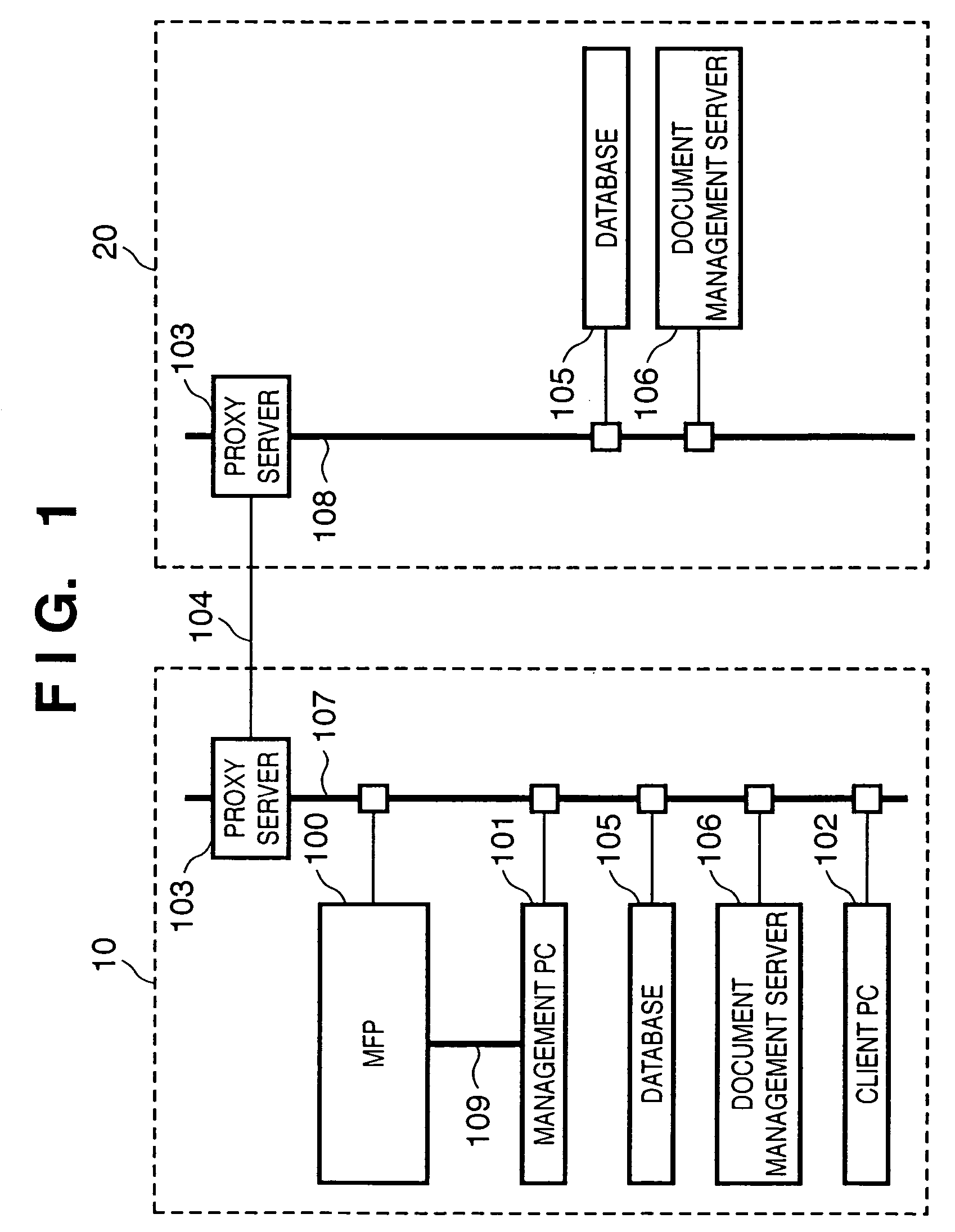
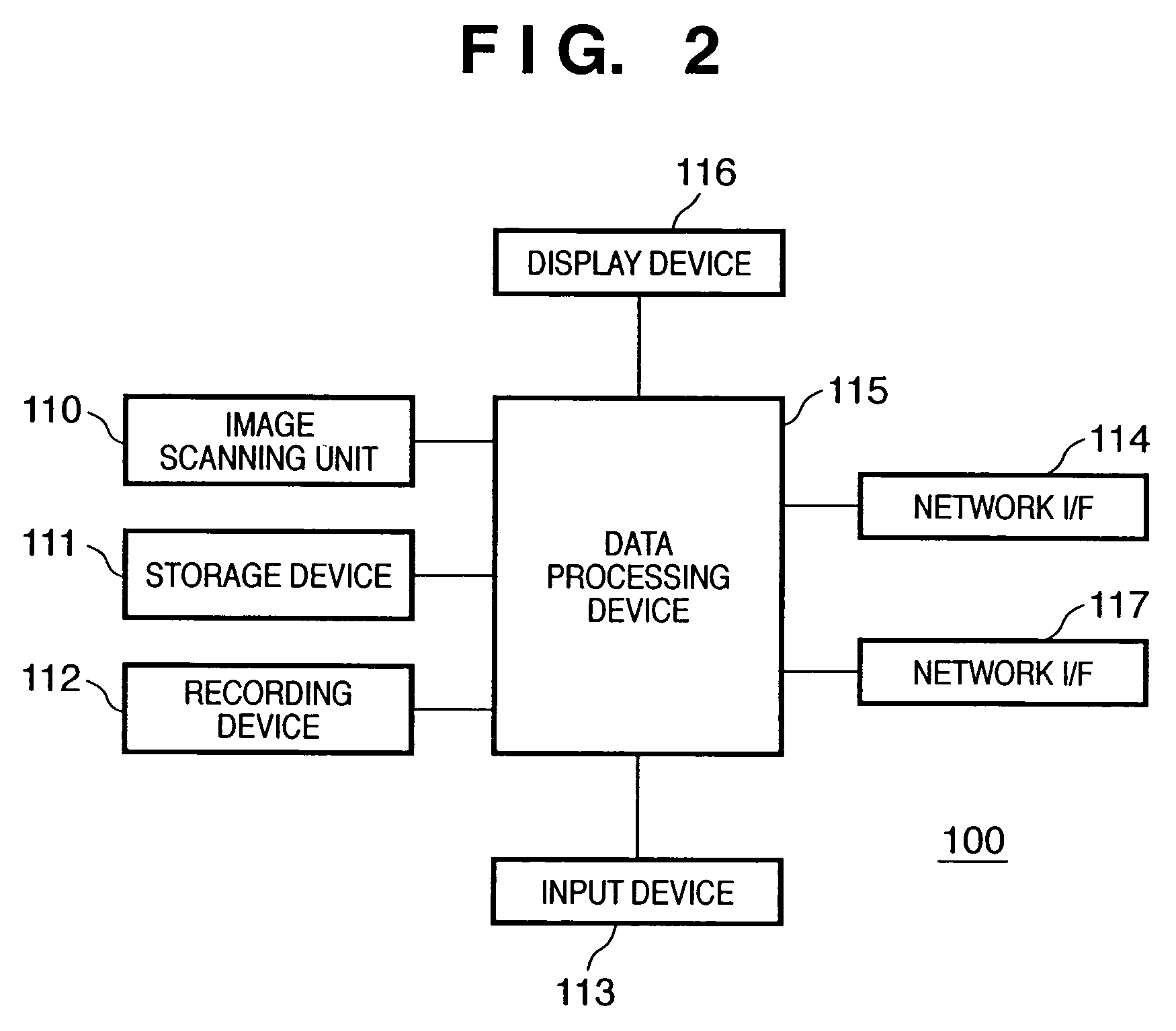
[0192]The arrangements of the image processing system and MFP according to this embodiment are the same as those in FIGS. 1 and 2 as in the first embodiment, and a detailed description thereof will be omitted.

>

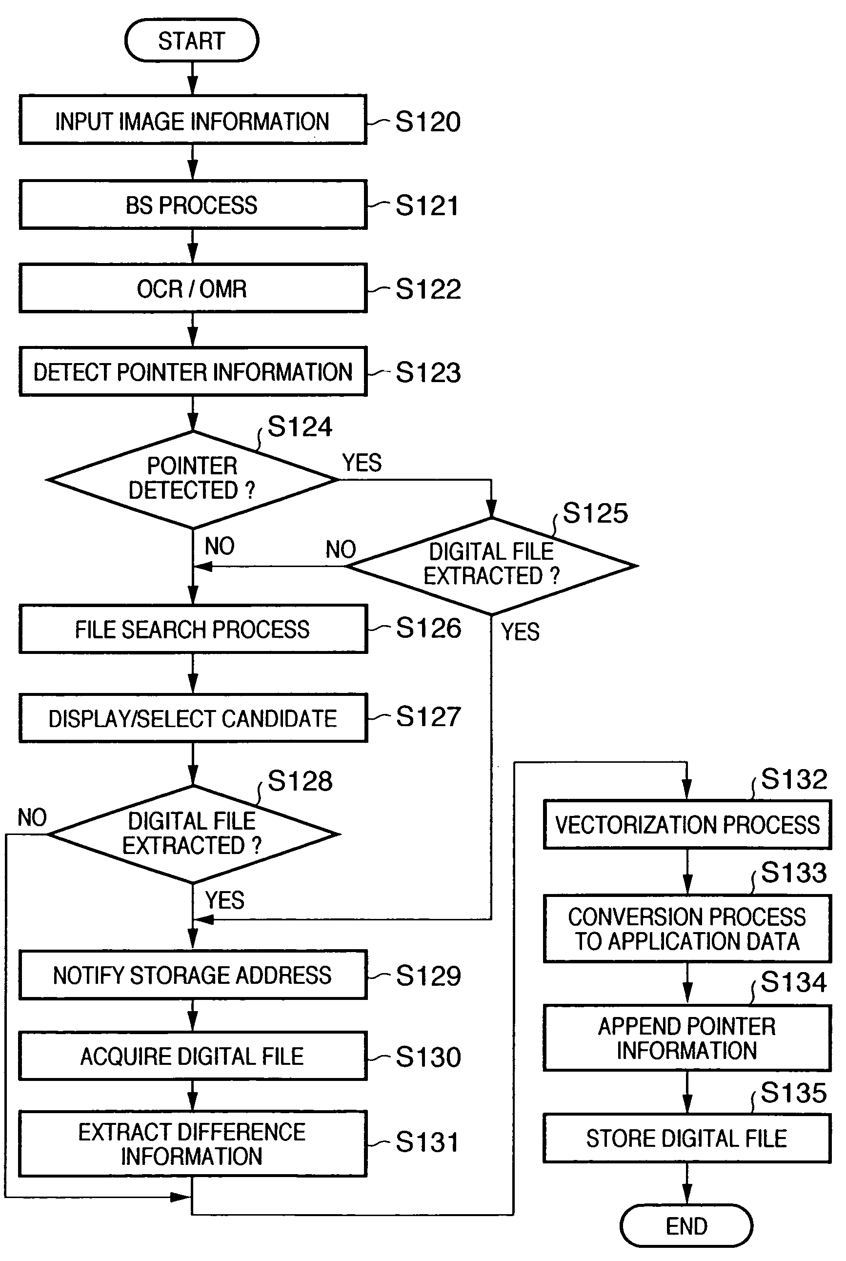
[0193]An overview of the entire image process according to the second embodiment will be described below using FIG. 23. Note that the processes in steps S2300 to S2308 in FIG. 23 are the same as those in steps S120 to S128 in FIG. 3, but all the steps will be explained in place of only different steps for the sake of easy understanding.

[0194]Referring to FIG. 23, the image scanning unit 110 of the MFP 100 (see FIG. 2) is enabled to scan one document in a raster order, and to obtain an 8-bit image signal of a 600 DPI in step S2300 associated with an image information input process. This image signal undergoes a pre-process by the data processing device 115, and is stored as image data for one page in the storage device 111. The CPU of the management PC 101 s...

third embodiment

C. Third Embodiment

[0217]Since the same image processing system and MFP 100 as those in the first embodiment can be applied, a description thereof will be omitted.

>

[0218]The third embodiment of the image processing method according to the present invention is implemented by respective steps in FIG. 24. Note that FIG. 24 includes the same processes as those included in the flow chart of FIG. 3, but they will be explained without being omitted for the sake of easy understanding.

[0219]Step S2401: The image scanning unit 110 of the MFP 100 is enabled to scan one document in a raster order, and to obtain an 8-bit image signal of a 600 DPI in an image information input process. The scanned image signal undergoes a pre-process by the data processing device 115, and is stored as image data for one page in the storage device 111. The flow advances to step S2402.

[0220]Step S2402 (block selection step): The management PC 101 separates regions of image data stored in the storage device 111 into...


PUM


Abstract

Stored digital data is searched for on the basis of an input image, difference information is extracted by comparing the retrieved digital data and the input image, and the difference information is composited to the digital data. Digital data generated by composition is stored. When no digital data is retrieved, the input image is converted into vector data, and the image that has been converted into the vector data is stored as digital data. Obtained region segmentation information and an input image are composited, the composite image is displayed on an operation screen of an MFP, and a rectangular block to be vectorized is designated as a specific region from the displayed region segmentation information. A user designates the specific region by designating rectangular blocks in an image using a pointing device.

Description

CLAIM OF PRIORITY[0001]The present application claims priority under 35 U.S.C. §119 from Japanese Patent Applications No. 2003-35113, entitled “An Image Processing Method” and filed on Feb. 13, 2003, No. 2003-35112, entitled “An Image Processing Method” and filed on Feb. 13, 2003, No. 2003-152050, entitled “An Image Processing Method” and filed on May 29, 2003, and No. 2003-121075, entitled “An Image Processing Method” and filed on Apr. 25, 2003, the entire contents of which are hereby incorporated by reference herein.FIELD OF THE INVENTION[0002]The present invention relates to an image process and, more particularly, to an image process for extracting handwritten information additionally written on an image of a document which is scanned by, e.g., a scanner, digital camera, or the like, an image process for converting the scanned image of the document into vector data that can be re-used by so-called document creation application software (e.g., Word or the like), and the like.BACK...

Claims


Application Information

Patent Timeline
Patent Type & Authority Patents(United States)
IPC IPC(8): G06K9/46G06F17/30G06V10/46H04N1/417
CPCG06F17/30271G06K9/00456G06K9/48H04N1/4177G06F16/56G06V30/413G06V10/46
Inventor OHTA, KEN-ICHITANIOKA, HIROSHIUSAMI, AKIHIROKANEDA, KITAHIROITO, HIROHIKOKATO, SHINICHIAKIBA, TOMOHIROKANATSU, TOMOTOSHIMISAWA, REIJITERAO, YOSHIHIDEUZAWA, MITSURU
Owner CANON KK
Why Eureka
Try Eureka