
Accelerometer having adjustable damping

a technology of accelerometer and damping force, which is applied in the direction of speed/acceleration/shock measurement, speed/acceleration/shock measurement, testing/calibration of speed/acceleration/shock measurement devices, etc., and can solve the problem of difficult to achieve balanced damping force in practi

Inactive Publication Date: 2008-07-01
HONEYWELL INT INC
View PDF11 Cites 10 Cited by
  • Summary
  • Abstract
  • Description
  • Claims
  • Application Information

AI Technical Summary

Benefits of technology

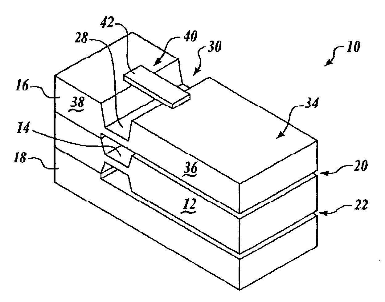
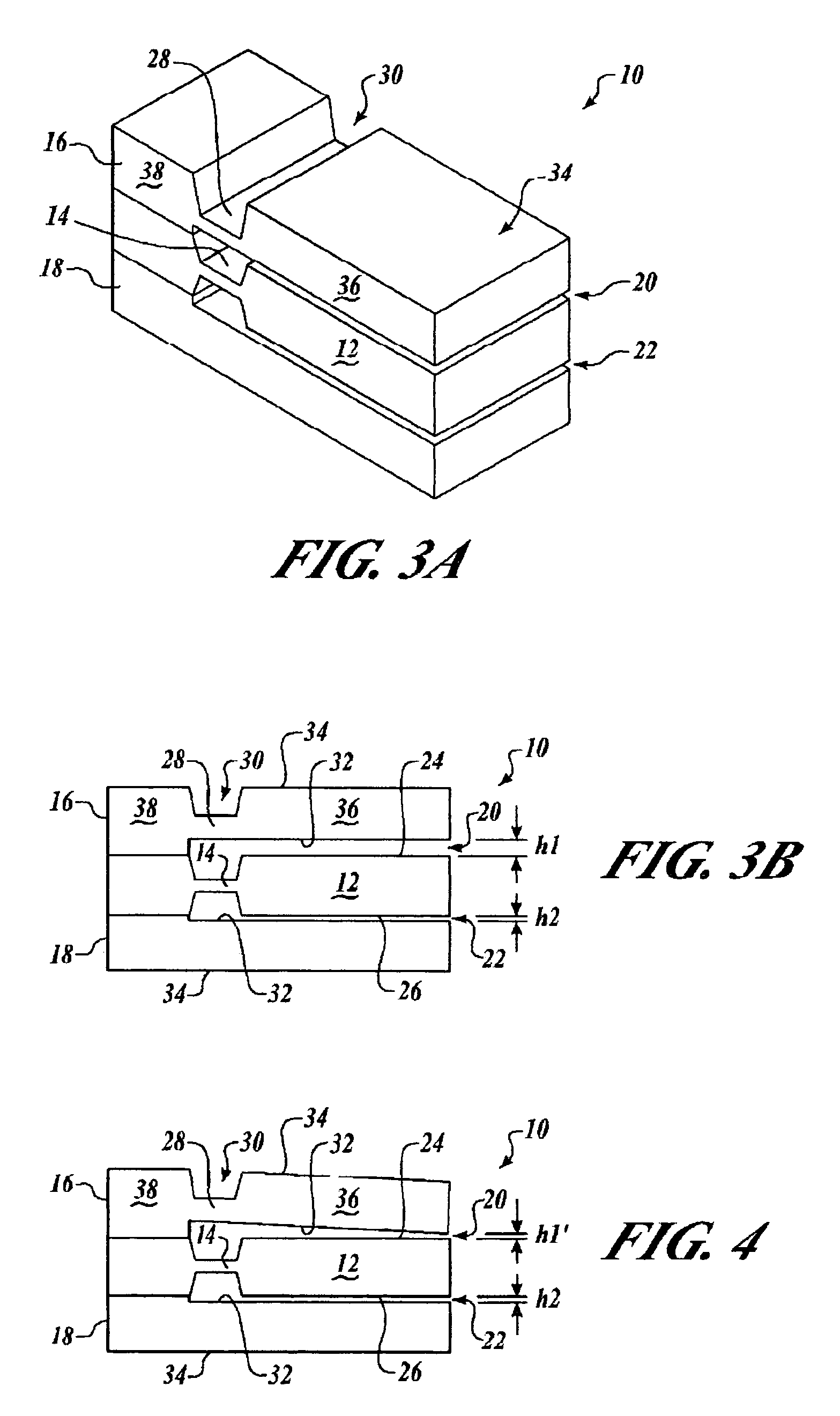
[0012]The present invention is an apparatus and method for overcoming limitations of the prior art by providing a means for adjusting one or both of the gas damping gaps formed between the proof mass and the first and second damping or “cover” plates and thereby equalizing the gas damping forces on the pendulum.

Problems solved by technology

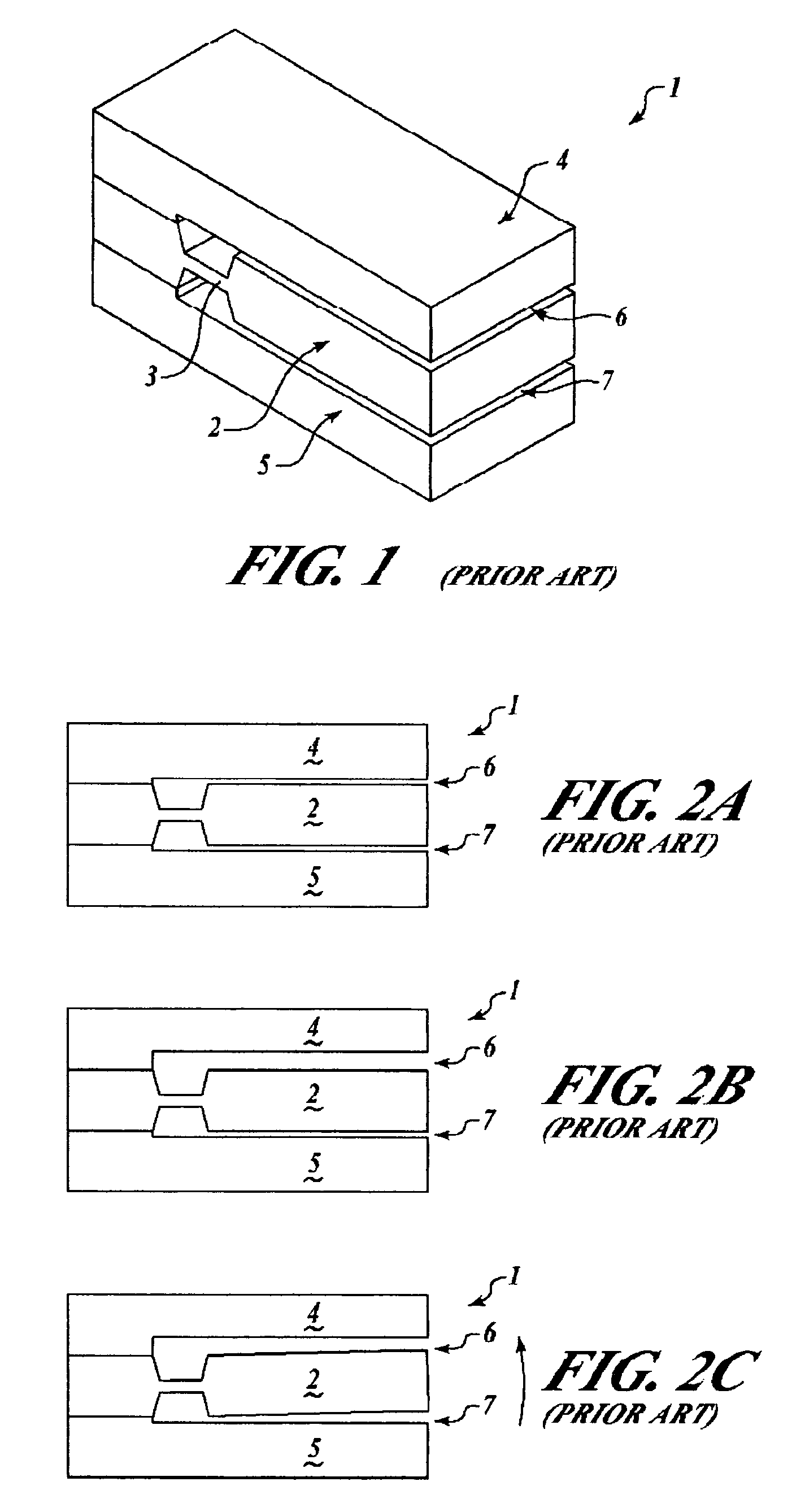
This cubic proportionality causes achievement of balanced damping forces to be very difficult in practice due to manufacturing tolerances.

Method used


Image

  • Accelerometer having adjustable damping
  • Accelerometer having adjustable damping
  • Accelerometer having adjustable damping

Examples


Embodiment Construction

[0027]In the Figures, like numerals indicate like elements.

[0028]The Figures illustrate the method and apparatus of the present invention for an accelerometer mechanism having a proof mass suspended between first and second damping or “cover” plates for out-of-plane motion in response to an acceleration input with first and second gas damping gaps being formed between the proof mass and the respective first and second damping plates. One or both of the first and second damping plates is structured with a flexure or hinge for being moved or bent between first and second positions relative to the proof mass for equalizing the first and second gas damping gaps. Retaining structure is coupled to the movable damping plate for retaining the damping plate in the second position relative to the proof mass.

[0029]FIGS. 3A and 3B illustrate the movable damping plate of the present invention embodied in a novel accelerometer mechanism 10 having a proof mass 12 suspended for out-of-plane motion ...


PUM


Abstract

An apparatus and method for an accelerometer mechanism having a proof mass that is suspended for out-of-plane motion between first and second damping plates, wherein at least one of the first and second damping plates is movable between first and second positions relative to the proof mass under the control of a position control structure that is coupled to the movable damping plate for positioning the damping plate in the second position relative to the proof mass.

Description

[0001]The invention described herein was made in the performance of work under Air Force Research Laboratories (AFRL) Contract No. F29601-03-C-0124. The Government may have rights to portions of this invention.FIELD OF THE INVENTION[0002]The present invention relates to acceleration and other force sensor devices and methods, and in particular to accelerometers and other force sensing devices having a proof mass suspended for out-of-plane motion and damping of the proof mass provided by damping plates (also known as “cover plates”) above and beneath the proof mass in such a way that the damping plates define thin gaps above and below the proof mass.BACKGROUND OF THE INVENTION[0003]Pendulous accelerometer and other force sensing devices are generally well-know. In particular, pendulous accelerometers are generally well-know as being macro-machined of quartz or another suitable material and having a tuning fork type sensor connected between the proof mass and the frame.[0004]FIG. 1 il...

Claims


Application Information

Patent Timeline
Patent Type & Authority Patents(United States)
IPC IPC(8): G01P21/00G01P15/00
CPCG01P15/0922G01P15/08G01P2015/0828
Inventor BECKA, STEPHEN F.
Owner HONEYWELL INT INC
Learn More