Optical laser projection system with speckle reduction element configured for out-of-plane motion

一种投影系统、斑点的技术,应用在利用投影装置图像重现器、光学、电气元件等方向,能够解决降低等问题

Inactive Publication Date: 2012-05-30
EASTMAN KODAK CO
View PDF12 Cites 4 Cited by
  • Summary
  • Abstract
  • Description
  • Claims
  • Application Information

AI Technical Summary

Problems solved by technology

The speckle reduction provided by the moving diffuser at the inner intermediate image plane (which is then imaged onto the screen) introduces various further problems, including reduced image quality (resolution or MTF), ), and the need for faster imaging optics to collect the diffused light

Method used


Image

  • Optical laser projection system with speckle reduction element configured for out-of-plane motion
  • Optical laser projection system with speckle reduction element configured for out-of-plane motion
  • Optical laser projection system with speckle reduction element configured for out-of-plane motion

Examples


Embodiment Construction

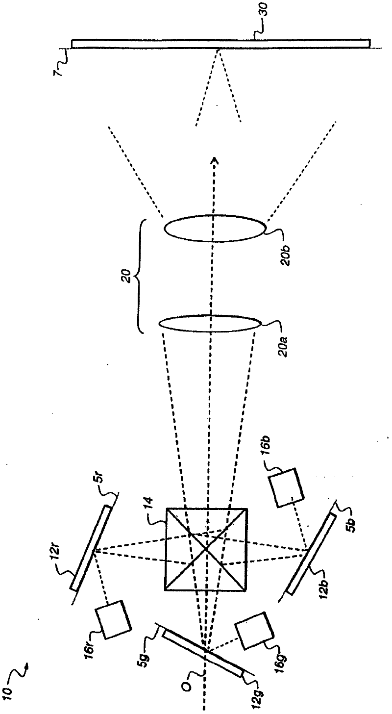
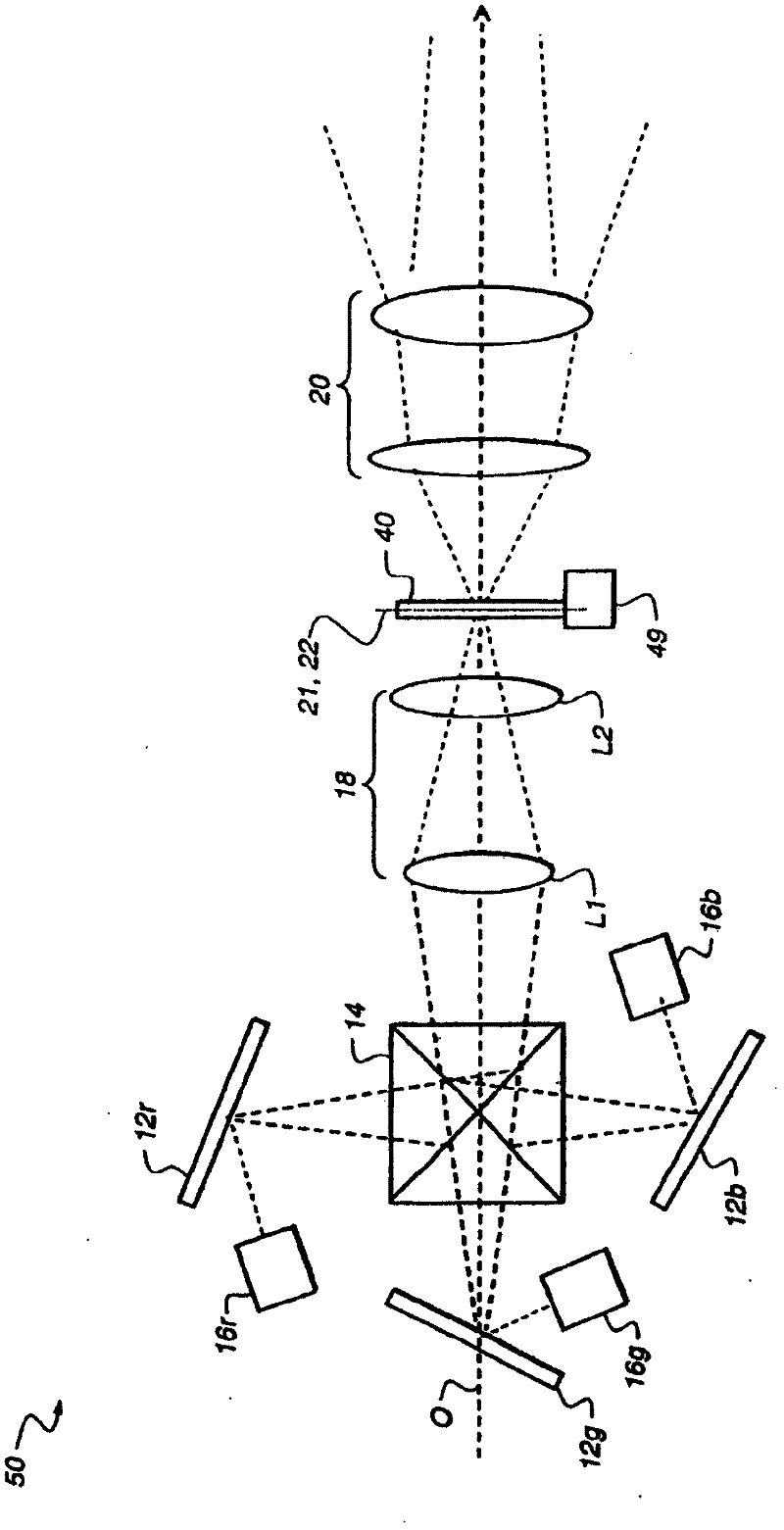
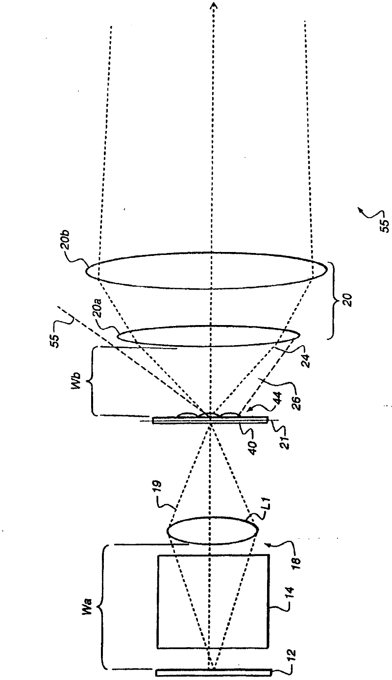
[0028] With regard to the detailed description that follows, it is to be understood that elements not specifically shown or described may take various forms well known to those skilled in the art. The figures shown and described herein are provided to clarify the principles of operation of embodiments according to the present invention and the relationship of elements along their respective optical paths, and may not show actual dimensions or proportions. Some exaggeration may be necessary to emphasize fundamental structural relationships or working principles. In some cases, elements normally located in the optical path of the projection device are not shown in order to more clearly describe the operation of the projection optics.

[0029] The invention includes combinations of the embodiments described herein. Reference to a particular embodiment and the like refers to features that occur in at least one embodiment of the invention. Individual references to "one embodiment...


PUM


Abstract

In a coherent light projection system including an image forming system (12), a relay system (18), a speckle reduction element (40), and a projection subsystem (20), the relay system can have a first f-number, and the projection subsystem can have a second f-number less than the first f-number. The relay system can have a first working distance, and the projection subsystem can have a second working distance less than the first working distance. The image forming system can project an initial image having a first size, and an intermediate image (22) can have a second size greater than or equal to the first size. The speckle reduction element can have a curved surface through which the intermediate image is transferred. The speckle reduction element can include a lenslet arrangement formed on a surface thereof. The speckle reduction element can be moved in a direction parallel to an optical axis of the speckle reduction element.

Description

technical field [0001] The present invention relates generally to digital image projection and, more particularly, to coherent light projection systems providing speckle compensation. Background technique [0002] Conventional projection lenses, which are used to project images onto a display surface, are designed with relatively fast optics. This is especially true for cinema projection, where traditional film projection lenses can be as fast as ~f / 1.8, and in the emerging technology of digital cinema, lenses are often ~f / 2.5. These low f / # numbers, and the corresponding high angles of light, are largely attributable to the use of large etendue light sources (such as various types of very bright arc lamps and similar light sources) ) coupled with (along with) the desire to utilize as much of this light as possible. [0003] In the case of digital cinema projection, through pixelated (pixelated) spatial light modulators (such as LCD and LCOS modulators, digital micromirror...

Claims


Application Information

Patent Timeline
Patent Type & Authority Applications(China)
IPC IPC(8): G02B27/48H04N9/31G02B5/02G02B3/00
CPCG03B21/2033H04N9/3161H04N9/3197G02B27/48G02B3/0056G03B21/20G03B21/208G02B5/02G03B33/06G03B21/14
Inventor B·D·西尔弗斯泰因G·E·诺萨德J·R·比特里R·梅茨格A·F·库尔茨
Owner EASTMAN KODAK CO
Why Eureka
Try Eureka