Multiple-spark ignition system for internal combustion engine
a multi-spark ignition and internal combustion engine technology, applied in the direction of electric ignition installation, machines/engines, mechanical equipment, etc., can solve the problems of worse fuel ignition performance, and achieve good fuel ignition performance
- Summary
- Abstract
- Description
- Claims
- Application Information
AI Technical Summary
Benefits of technology
Problems solved by technology
Method used
Image
Examples
first embodiment
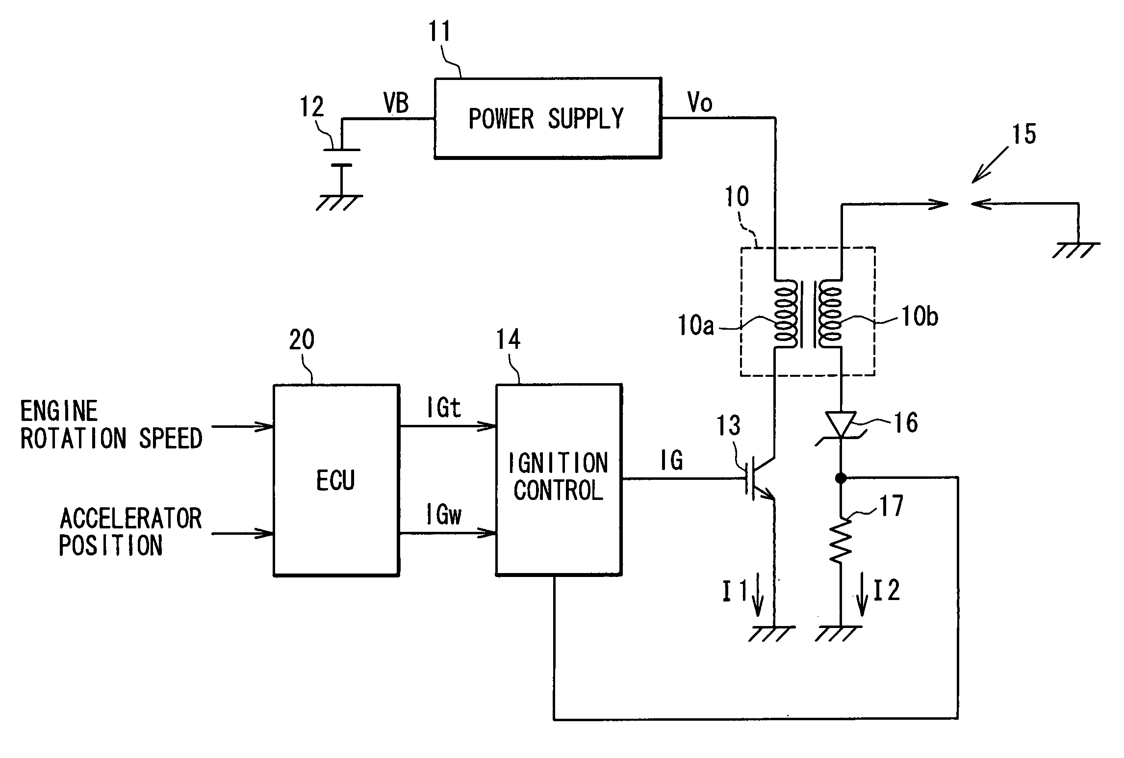
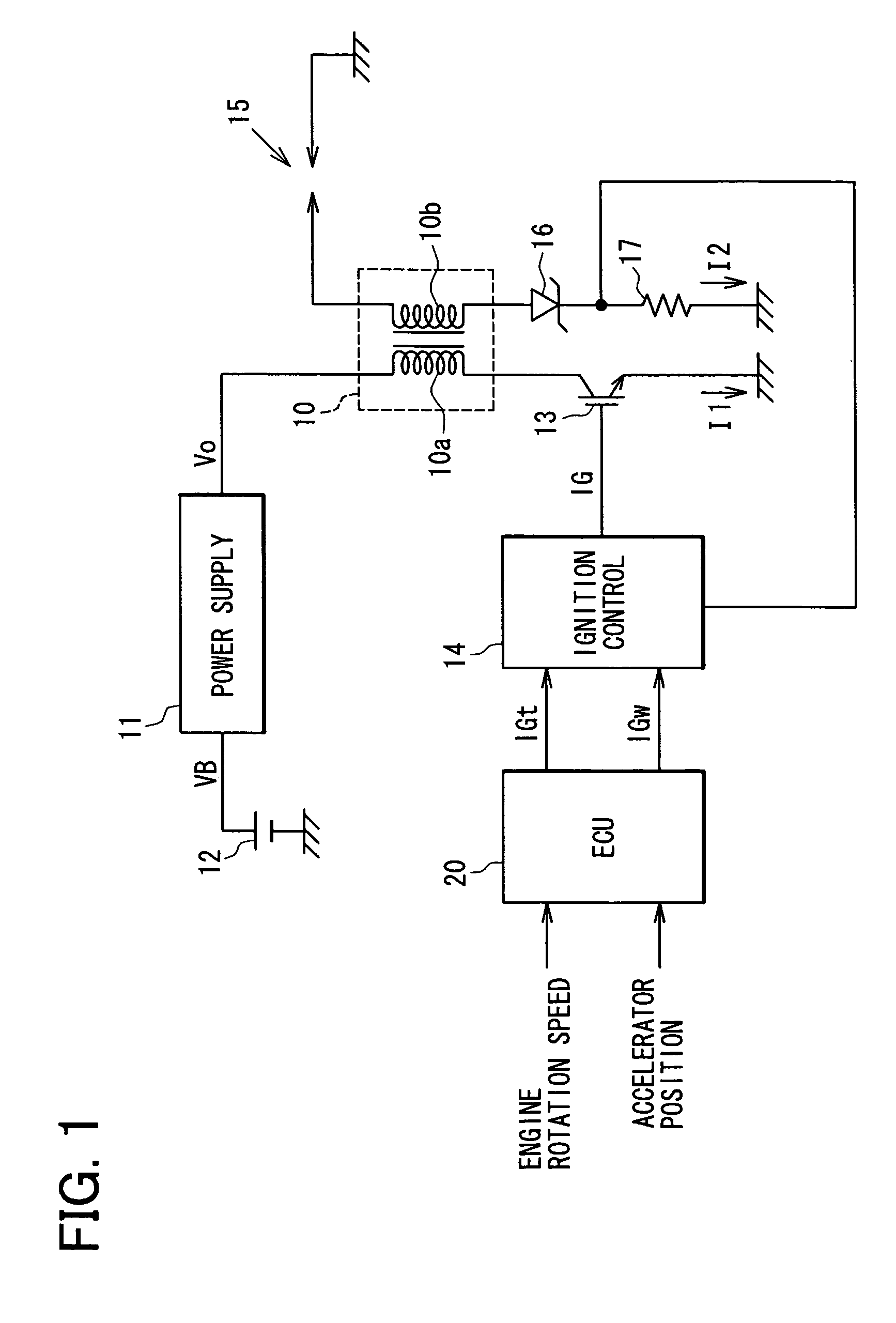
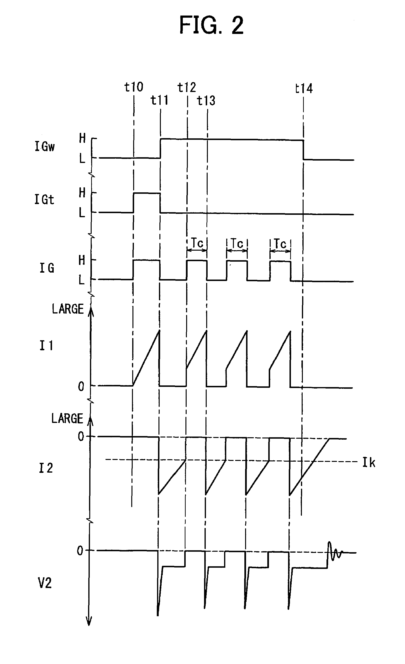
[0030]An ignition system according to the invention will be described with reference to FIGS. 1-6A and 6B.
[0031]As shown in FIG. 1, the ignition system includes an ignition coil 10, a power supply circuit 11, a battery 12, an insulated gate bipolar transistor (hereinafter referred to as the IGBT) 13, an ignition control circuit 14, a spark plug 15, a zener diode 16, a current measuring resistor 17, an ECU 20, etc.
[0032]The ignition coil 10 has a primary coil 10a and a secondary coil 10b. The primary coil 10a has a pair of ends, one of which connected via the power supply circuit 11 to a high side (e.g. 12 V) terminal of the battery 12 and the other of which is connected to a ground via the IGBT 13.
[0033]The IGBT 13 has a gate connected to the ignition control circuit 14, which controls the switching operation of the IGBT 13. The power supply circuit 11 is constituted of a common boosting DC-DC converter that includes an inductor, a switching element and a capacitor to provide a volt...
second embodiment
[0045]An ignition system according to the invention will be described with reference to FIGS. 7 and 8.
[0046]Incidentally, the same reference numeral as the first embodiment represents the same or substantially the same portion, part or component as the first embodiment, hereafter.
[0047]As shown in FIG. 7, the ignition system includes a capacitor-discharge circuit (hereinafter referred to as the CD circuit) 30 in addition to the ignition coil 10, power supply circuit 11, battery 12, the IGBT 13, the ignition control circuit 14, the spark plug 15, the current measuring resistor 17 and the an ECU 20. The zener diode 16 that is connected in series with the current measuring resistor 17 is replaced by a backflow prevention diode 35 that is connected in series with the primary coil 10 and the IGBT 13. It may be considered that the CD circuit 30 is included in the power supply circuit 11.
[0048]The CD circuit 30 includes a series circuit of an energy accumulation coil 31 and a second IGBT 3...
PUM
 Abstract
Description
Claims
Application Information
 - R&D
- Intellectual Property
- Life Sciences
- Materials
- Tech Scout
- Unparalleled Data Quality
- Higher Quality Content
- 60% Fewer Hallucinations
Browse by: Latest US Patents, China's latest patents, Technical Efficacy Thesaurus, Application Domain, Technology Topic, Popular Technical Reports.
© 2025 PatSnap. All rights reserved.Legal|Privacy policy|Modern Slavery Act Transparency Statement|Sitemap|About US| Contact US: help@patsnap.com


