Eureka AIR delivers breakthrough ideas for toughest innovation challenges, trusted by R&D personnel around the world.

Composite oxide, process for producing the same, and exhaust gas reducing co-catalyst

Active Publication Date: 2007-07-24
TOYOTA CENT RES & DEV LAB INC
View PDF29 Cites 19 Cited by
  • Summary
  • Abstract
  • Description
  • Claims
  • Application Information

AI Technical Summary

Benefits of technology

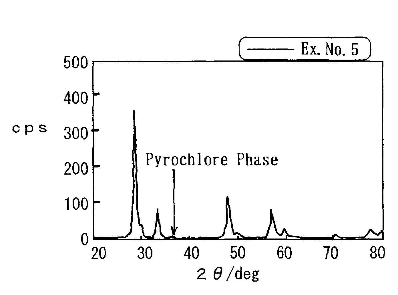
[0007]In addition, since the exhaust gas emission control has been strengthened recently, it has been required strongly to purify an exhaust gas even in a very short period of time after starting an engine. In order to do so, it is required to activate the catalysts at a much lower temperature and to purify the emission-controlled components. Among them, a co-catalyst, in which Pt is loaded on CeO2, is excellent in terms of the performance for purifying CO starting at a low temperature. When such a co-catalyst is used, the CO-adsorption poisoning of Pt is relieved by igniting CO at a low temperature, and the igniting ability of HC is enhanced. Further, with these advantageous effects, the warm-up of the catalyst surface is facilitated, and accordingly it is possible to purify HC from a low temperature region. Furthermore, in this co-catalyst, H2 is produced by a water gas shift reaction in a low temperature region, and consequently it is possible to reduce and purify NOx by the reactions of H2 and NOx from a low temperature region.
[0008]However, the conventional co-catalyst, in which Pt, etc., is loaded on CeO2, lacks the durability in actual exhaust gases. It is not practical because CeO2 causes the sintering by heat. In order to use it in actual exhaust gases, it is necessary to upgrade the heat resistance without losing the properties of CeO2. Moreover, accompanied by the sintering of CeO2, Pt causes the granular growth so that the activity decreases. Hence, it has been required to stabilize Pt loaded on CeO2.
[0009]Moreover, even in a 3-way catalyst which includes CeO2 in its support, its OSC, which is revealed by CeO2, lowers when it is exposed to a high temperature. The disadvantage is caused by the sintering of CeO2, the granular growth of the noble metal loaded thereon, the oxidation of the noble metal, the solving of Rh in CeO2, and so on. Thus, in a catalyst which exhibits a low OSC (or which has a small CeO2 content), the novel metal is likely to be exposed to a fluctuating atmosphere, and the deterioration (e.g., the agglomeration or solving) of the noble metal is furthermore facilitated.
[0010]Therefore, in Japanese Unexamined Patent Publication (KOKAI) No. 8-215,569, there is disclosed a technology using a Ceo2—ZrO2 composite oxide which is prepared from a metallic alkoxide. Since the CeO2—ZrO2 composite oxide, which is prepared from the metallic alkoxide by a sol-gel method, makes a solid solution in which Ce and Zr are composited at atomic level or molecular level, it is improved in terms of the durability and securely exhibits a high OSC from initial to post-durability service.
[0011]It is possible to produce such a composite oxide by preparing oxide precursors, which include a plurality of metallic elements, by an alkoxide method, a co-precipitation method, and the like, and by calcining them thereafter. Among them, since the co-precipitation method is less expensive in terms of the material cost compared to that of the alkoxide method, it effects an advantage in that the resulting composite oxide is less expensive. Hence, the co-precipitation method has been used widely in the production of composite oxides.
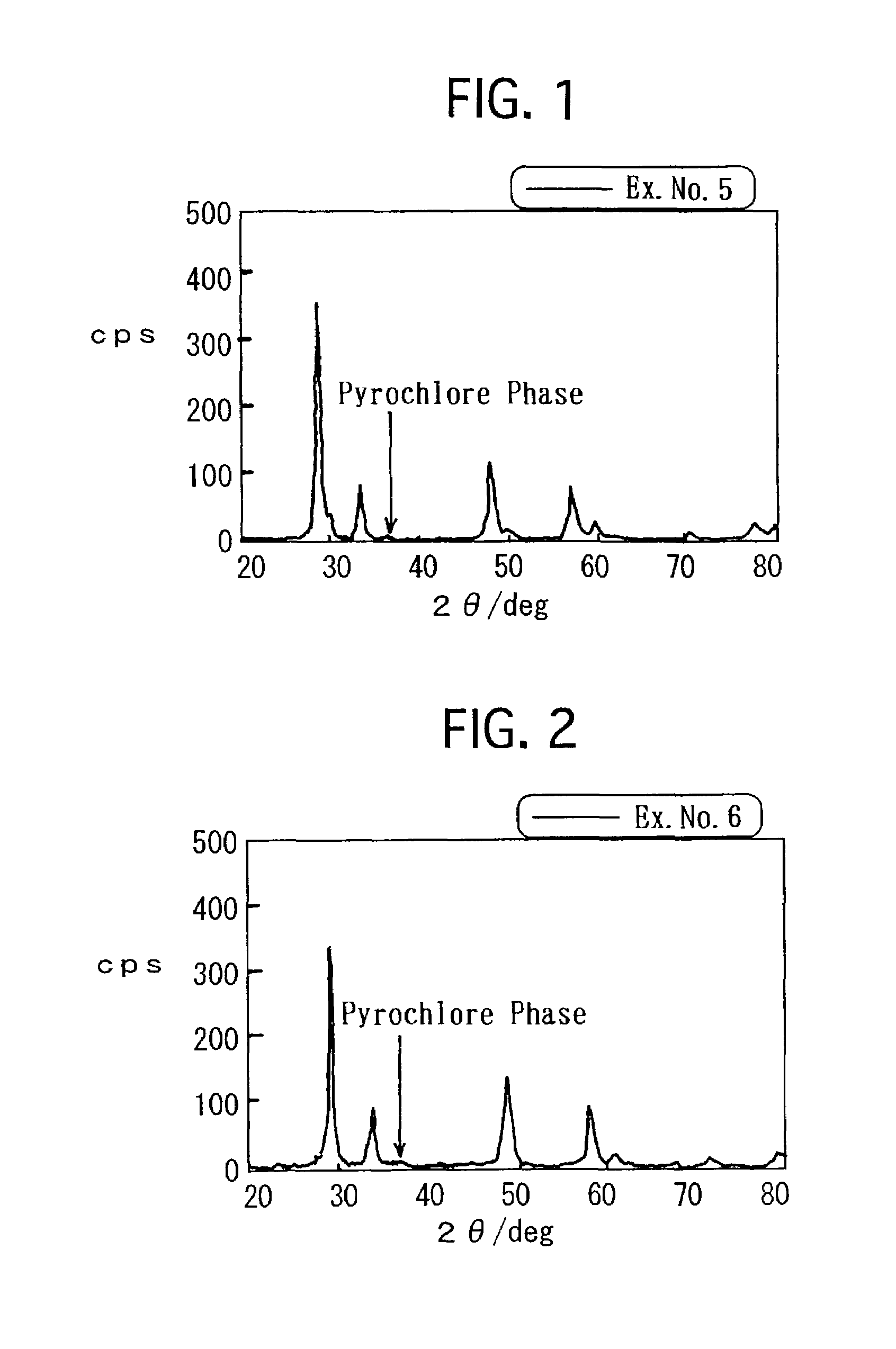
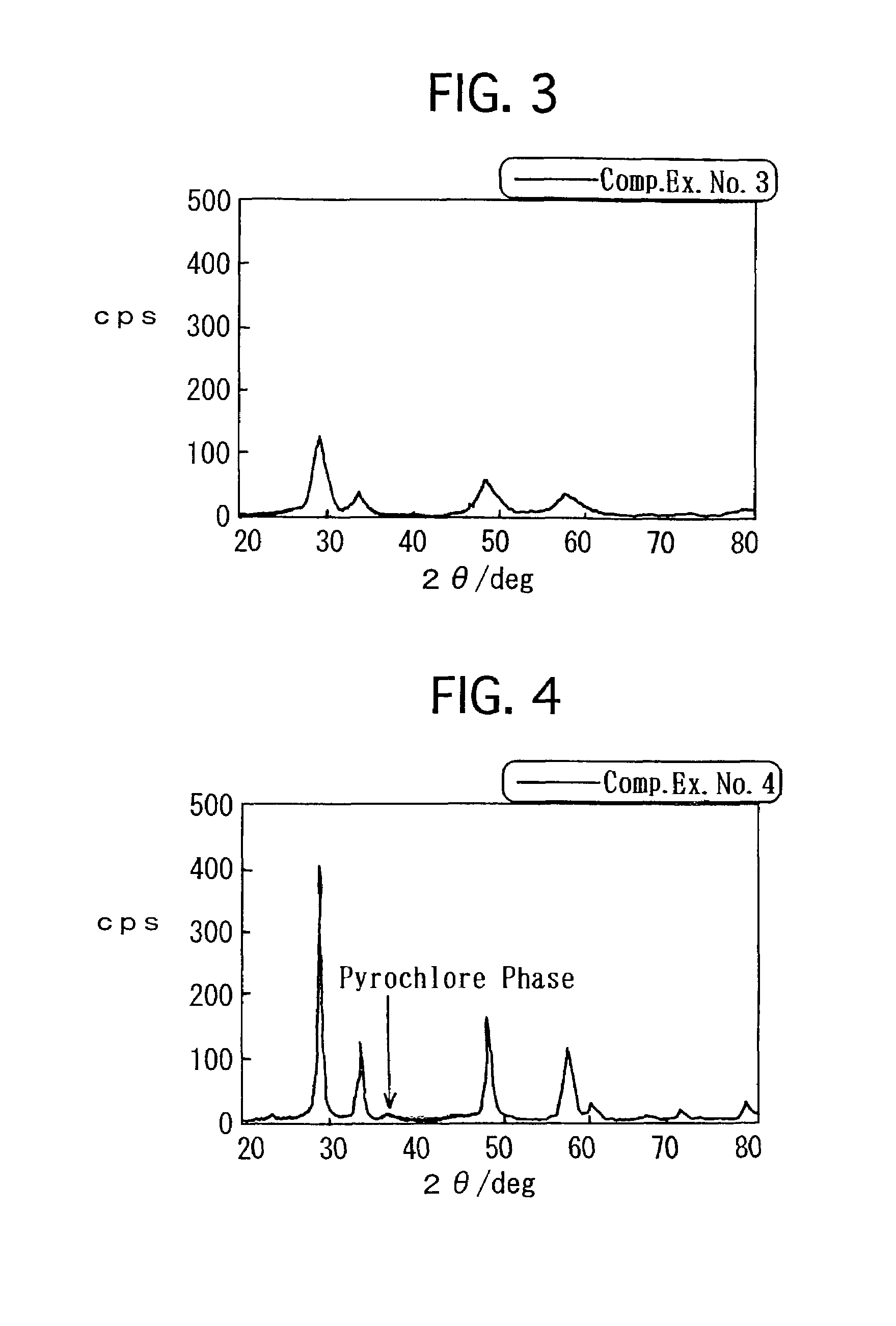
[0012]However, the composite oxide, which is set forth in Japanese Unexamined Patent Publication (KOKAI) No. 8-215,569, is still insufficient in terms of the OSC. Consequently, it has been required to furthermore improve the OSC. Hence, in Japanese Unexamined Patent Publication (KOKAI) No. 11-165,067, there is set forth a process in which precipitates are formed out of a solution, including a cerium (III) salt and a zirconium (IV) salt, by a co-precipitation method and the resulting precipitates are heated to and held at a temperature of from 800 to 1,000° C. in an inert atmosphere or a non-oxidizing atmosphere. By the process, the resulting composite oxide has an X-ray diffraction peak which is derived from a pyrochlore phase, and exhibits a high OSC.

Problems solved by technology

However, in the conventional catalyst for purifying an exhaust gas, there arise the decrement of the specific surface area of the support by sintering and the granular growth of the noble metal when it is subjected to a high temperature exceeding 800° C. Moreover, since the OSC, possessed by CeO2, decreases as well, there has been a drawback in that the purifying performance of the conventional catalyst degrades sharply.
However, the conventional co-catalyst, in which Pt, etc., is loaded on CeO2, lacks the durability in actual exhaust gases.
It is not practical because CeO2 causes the sintering by heat.
The disadvantage is caused by the sintering of CeO2, the granular growth of the noble metal loaded thereon, the oxidation of the noble metal, the solving of Rh in CeO2, and so on.
However, the composite oxide, which is set forth in Japanese Unexamined Patent Publication (KOKAI) No. 8-215,569, is still insufficient in terms of the OSC.
However, in the process, since the precipitates are heated to and held at a temperature of from 800 to 1,000° C., it is inevitable to decrease the specific surface area of the CeO2—ZrO2 composite oxide.
Accordingly, when the CeO2—ZrO2 composite oxide is used to make an exhaust gas reducing co-catalyst, it is difficult to attain practically high reducing activities.
Accordingly, it is difficult to attain practical performance as an exhaust gas reducing co-catalyst.

Method used


Image

  • Composite oxide, process for producing the same, and exhaust gas reducing co-catalyst
  • Composite oxide, process for producing the same, and exhaust gas reducing co-catalyst
  • Composite oxide, process for producing the same, and exhaust gas reducing co-catalyst

Examples


examples

[0064]Hereinafter, the present invention will be described in detail with reference to specific examples and comparative examples.

example no.1

Example No. 1

[0065]Aluminum nitrate nona-hydrate (Al(NO3)3.9H2O), cerium nitrate hexa-hydrate (Ce(NO3)4.6H2O) and zirconyl oxynitrate di-hydrate (ZrO(NO3)2.2H2O) were solved in pure water in predetermined amounts, respectively. While stirring the mixture aqueous solution vigorously, ammonium water was added to the mixture aqueous solution. The ammonium water included NH3 in an amount as much as 1.2 times by mole for the neutralization equivalent of the respective nitrates. After the thus precipitated precursors were evaporated to dry at 150° C., the precursors were further dried at 300° C. for 3 hours. Thereafter, the precursors were calcined at 500° C. for 1 hour, and were further heat-treated at 700° C. for 5 hours. Thus, a ternary composite oxide was prepared. Note that the composition ratio of the composite oxide was Al2O3:CeO2:ZrO2=1:0.9:1.1 by mol.

[0066]Then, an aqueous solution of platinum (II) dinitro diammine having a predetermined concentration was impregnated into the res...

example no.2

Example No. 2

[0068]Except that the ternary composite oxide, on which Pt was loaded in the same manner as Example 1, was reduced in the N2 gas atmosphere, which included H2 in an amount of 5% by volume, at 900° C. for 5 hours, a pelletized co-catalyst of Example No. 2 was prepared in the same manner as Example No. 1.


PUM

PropertyMeasurementUnit
Temperatureaaaaaaaaaa
Specific surface areaaaaaaaaaaa

Abstract

A composite oxide includes CeO2, ZrO2 and a metallic oxide being free from reacting with CeO2 and ZrO2 at 700° C. or more, preferably at 900° C. or more and further preferably at 1,000° C. or more. The composite oxide has a regulatory oriented phase, such as a pyrochlore phase, etc., in which at least a part of Ce cations and Zr cations are oriented regularly. The composite oxide makes a catalytic support. The CeO2—ZrO2 composite oxide and the reaction-free metallic oxide make barriers each other which suppress the granular growth when the composite oxide is subjected to high-temperature heat in a reducing heat treatment to form the regulatory oriented phase. The regulatory oriented phase improves the oxygen storage-and-release capability of the catalytic support. Thus, it is possible to simultaneously attain a large a specific surface area and a high oxygen storage-and-release capability.

Description

BACKGROUND OF THE INVENTION[0001]1. Field of the Invention[0002]The present invention relates to an exhaust gas reducing co-catalyst which not only has a sufficiently large specific surface area but also a high oxygen storage-and-release capability (hereinafter abbreviated to as “OSC”), and which is good in terms of the durability, a composite oxide which is used as a support for the exhaust gas reducing co-catalyst, and a process for producing the same.[0003]2. Description of the Related Art[0004]Conventionally, as a catalyst for purifying an automotive exhaust gas, a 3-way catalyst has been used which oxidizes CO and HC and reduces NOx in the exhaust gas simultaneously. As for such a 3-way catalyst, for example, a catalyst has been known widely in which a support layer, being composed of γ-Al2O3, is formed on a heat resistant honeycomb substrate, being composed of cordierite, etc., and a noble metal, such as platinum (Pt), rhodium (Rh), etc., is loaded in the support layer.[0005]B...

Claims


Application Information

Patent Timeline
IPC IPC(8): B01J23/00C01G49/00C04B35/48B01D53/94B01J21/06B01J23/10B01J23/63B01J35/10B01J37/03
CPCB01J23/10B01J23/63B01J35/002B01J37/03B01D2255/1021B01D2255/2065B01D2255/20715B01D2255/407B01D2255/908B01J21/066B01J35/023B01J35/1014F01N2570/16B01J35/30B01J35/40B01J35/613
Inventor MORIKAWA, AKIRANAGAI, YASUTAKATANABE, TOSHITAKASUZUKI, TADASHISUDA, AKIHIKOSOBUKAWA, HIDEO
Owner TOYOTA CENT RES & DEV LAB INC
Why Eureka
Eureka Blog
Learn More