
Ophthalmic testing unit and ophthalmic testing equipment

a technology of ophthalmic testing and ophthalmic equipment, which is applied in the field of ophthalmic testing units, can solve the problems of ineffective examination proceeding, inability to give correct answers, and inability to accurately measure the accuracy of the examination

Inactive Publication Date: 2008-07-01
KOWA CO LTD
View PDF8 Cites 11 Cited by
  • Summary
  • Abstract
  • Description
  • Claims
  • Application Information

AI Technical Summary

Benefits of technology

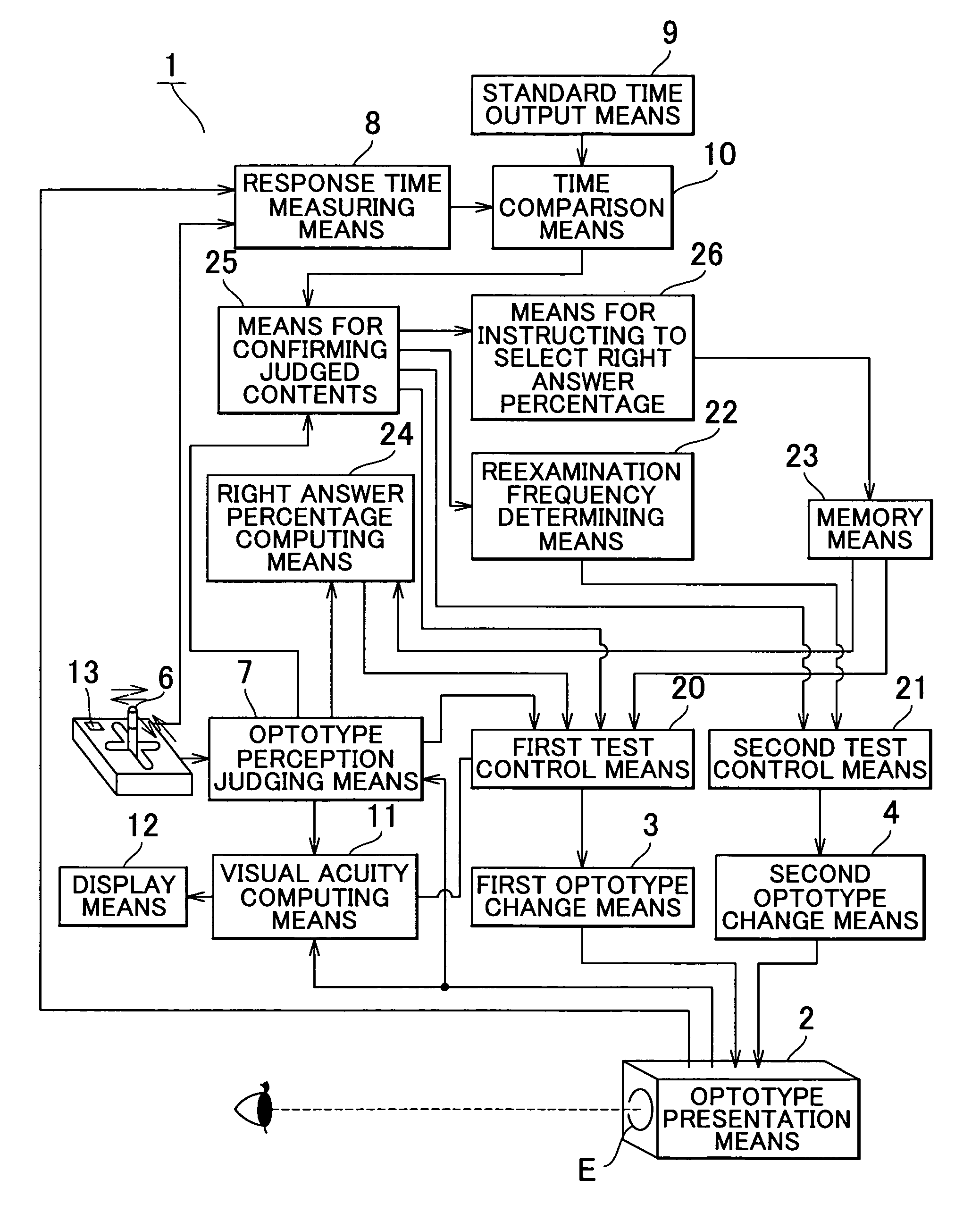
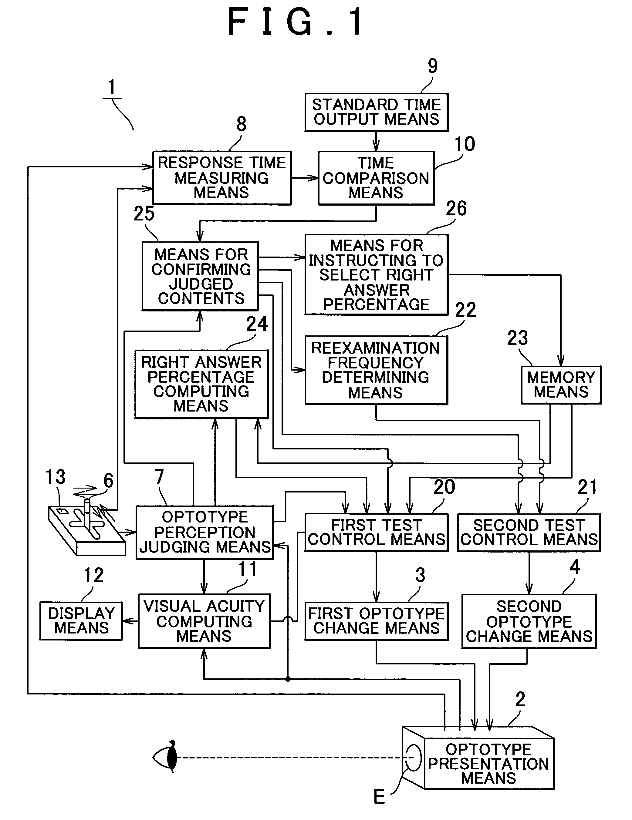
The invention is an ophthalmic testing unit that can accurately measure a person's visual acuity by presenting optotypes to the person and measuring the time it takes for them to perceive the optotype. The testing unit includes a display for showing the optotype and a response time measuring device. The testing unit can also adjust the difficulty of the optotype based on the person's response time. This allows for a more accurate measurement of visual acuity. Additionally, the testing unit can re-examine the optotype if the person has difficulty in perceiving it the first time, improving the accuracy of the visual acuity test.

Problems solved by technology

In addition, an examinee may give a wrong answer due to error operation of the joystick lever 203 even if the examinee fully recognizes the optotype.
Problems remain if the visual acuity is determined only by right or wrong answer of the result of perception of optotype in such cases.
A conventional device measures a visual field without considering a time till the operation of the response switch 403, so that proceeding of the examination is not effective.

Method used


Image

  • Ophthalmic testing unit and ophthalmic testing equipment
  • Ophthalmic testing unit and ophthalmic testing equipment
  • Ophthalmic testing unit and ophthalmic testing equipment

Examples


first embodiment

[0120]In this embodiment, the visual field device 301 is comprised of the stimulus display means 302 as shown in FIG. 6 and a control unit as shown in FIG. 7.

[0121]Of both, the stimulus display means 302 is provided with the stimulus presentation portion 320 which is comprised of the projection optical system 320A for projecting the stimuli A and the semi-sphere visual field dome (projection member) 320B on which the stimuli are projected so as to display the stimuli A in the visual field of an examinee.

[0122]The projection optical system 320A is comprised of a stimulus projection lump 3201 (halogen lamp) which is a light source, a reflecting mirror 3200 which is arranged at a rear side of the lamp 3201, a condenser lens 3202 which is arranged on a front side of the lamp 3201 for condensing, an aperture 3203 for determining a shape or a size of the stimulus A (will be described later in detail), a color filter turret 3204 for determining a color of the stimulus A (will be described ...


PUM


Abstract

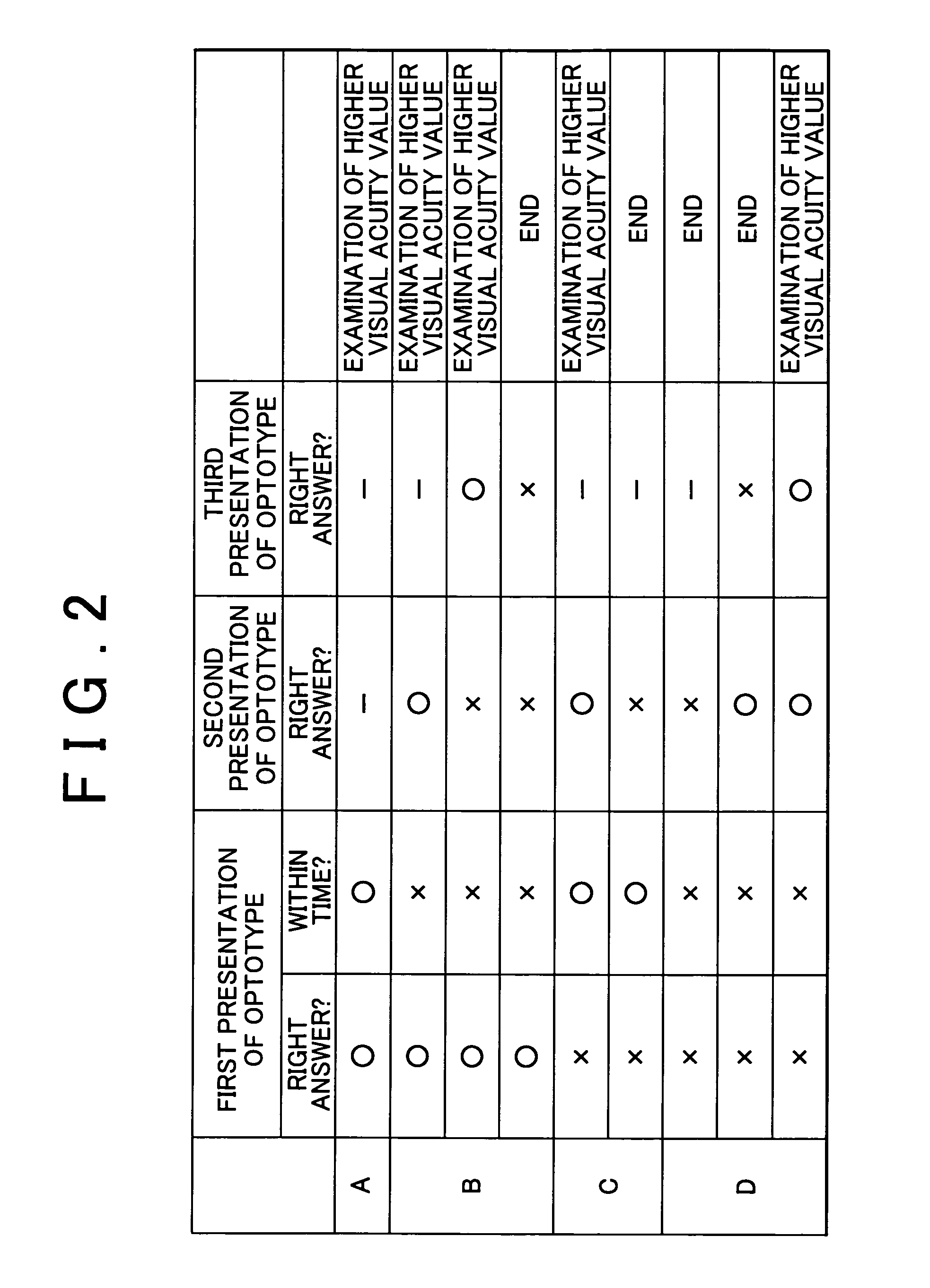
When a Landolt ring optotype is presented in a visual acuity testing unit, an examinee answers a position of a slit of the optotype through an operation of a joystick lever or the like. If an examinee gives a right answer within a standard time at a first presentation of optotype, examination at a higher visual acuity grade is executed by presenting a smaller Landolt ring optotype. In case of a right answer over the standard time, reexamination at the same visual acuity grade is executed twice at the most. If a right answer is given at least once, examination at a higher visual acuity grade is executed. In case of a wrong answer within the standard time at a first presentation of optotype, reexamination at the same visual acuity is executed only once. If the right answer is given at this reexamination, examination at a higher visual acuity grade is executed. Reexamination is thus executed, so that the result of the examination is correct. In addition, the examination time can be shortened since necessary number of times of reexaminations is minimum.

Description

TECHNICAL FIELD[0001]This invention relates to an ophthalmic testing unit for measuring a visual acuity and a visual field of an examinee. And, the invention relates to a visual acuity testing device for testing a visual acuity and a visual acuity testing equipment with the visual acuity testing devices. Besides, the invention relates to a visual field device for measuring a visual field of an examinee.BACKGROUND ART[0002]A conventional automatic visual acuity testing device which has been proposed shows optotypes to an examinee and automatically tests a visual acuity of the examinee (see Japanese patent application (publication No. H09-1187423, for instance).[0003]FIG. 5 is a perspective view showing appearances of a conventional structure of such an automatic visual acuity testing device. A reference numeral 200 is an optotype portion for showing an optotype, such as a Landolt ring, which is inside a housing 201, and a reference numeral 202 is a test window through which an examin...

Claims


Application Information

Patent Timeline
Patent Type & Authority Patents(United States)
IPC IPC(8): A61B3/02
CPCA61B3/028
Inventor HARA, TAKUYASUZUMURA, YOSHIKATSU
Owner KOWA CO LTD
Learn More