Method and apparatus for electric clamping

a technology of electric clamping and die casting machine, which is applied in the direction of manufacturing tools, application, and foundation moulding apparatus, etc., can solve the problems of affecting the mold itself, and affecting the clamping process, so as to shorten the molding cycle time

Active Publication Date: 2008-07-01
TOSHIBA MASCH CO LTD
View PDF4 Cites 0 Cited by
  • Summary
  • Abstract
  • Description
  • Claims
  • Application Information

AI Technical Summary

Benefits of technology

[0010]It is an object of the present invention to achieve the compatibility of making an efficient electric clamping process using a die casting machine, and security of the core-drawing-in process to be performed in parallel with the clamping process.
[0011]The present invention was made to achieve the above-described object, and provides a method and a apparatus for electric clamping using a die casting machine, which performs the clamping process in parallel with the core-drawing-in process such that the core-drawing-in process can be completed securely without damaging the mechanisms of the mold and core.
[0013]According to the present invention, a check point is provided in the course of closing a mold in the clamping process, and the clamping process is continued while confirming the safety detected by a signal obtained from the check point. Thus, shortening the molding cycle time in the clamping process due to high speed opening and closing of the mold utilizing a feature of the electric clamping unit can be attained, as well as, damages of the clamping mechanism of the die casting machine, and the mechanisms of the mold and core due to premature clamping occurring before completion of the core-drawing-in process can be securely prevented.

Problems solved by technology

In the case of setting a core in a mold, there is an issue on the relation to the clamping process.
In the former methods, while a safe and secure clamping operation can be provided, the clamping process and the core-drawing-in process must be arranged in series, leading to lengthen the cycle time of the molding.
However, in the latter methods, when the core-drawing-in process is complicated, the core, the mechanism to draw the core into the mold, or the mold itself may be damaged unless the core-drawing-in process has completed before the final mold closing step of the clamping process.

Method used


Image

  • Method and apparatus for electric clamping
  • Method and apparatus for electric clamping
  • Method and apparatus for electric clamping

Examples


Embodiment Construction

[0018]A first embodiment of the present invention will be described in terms of a clamping method using an electrically-driven die casting machine with reference to FIGS. 1 to 4.

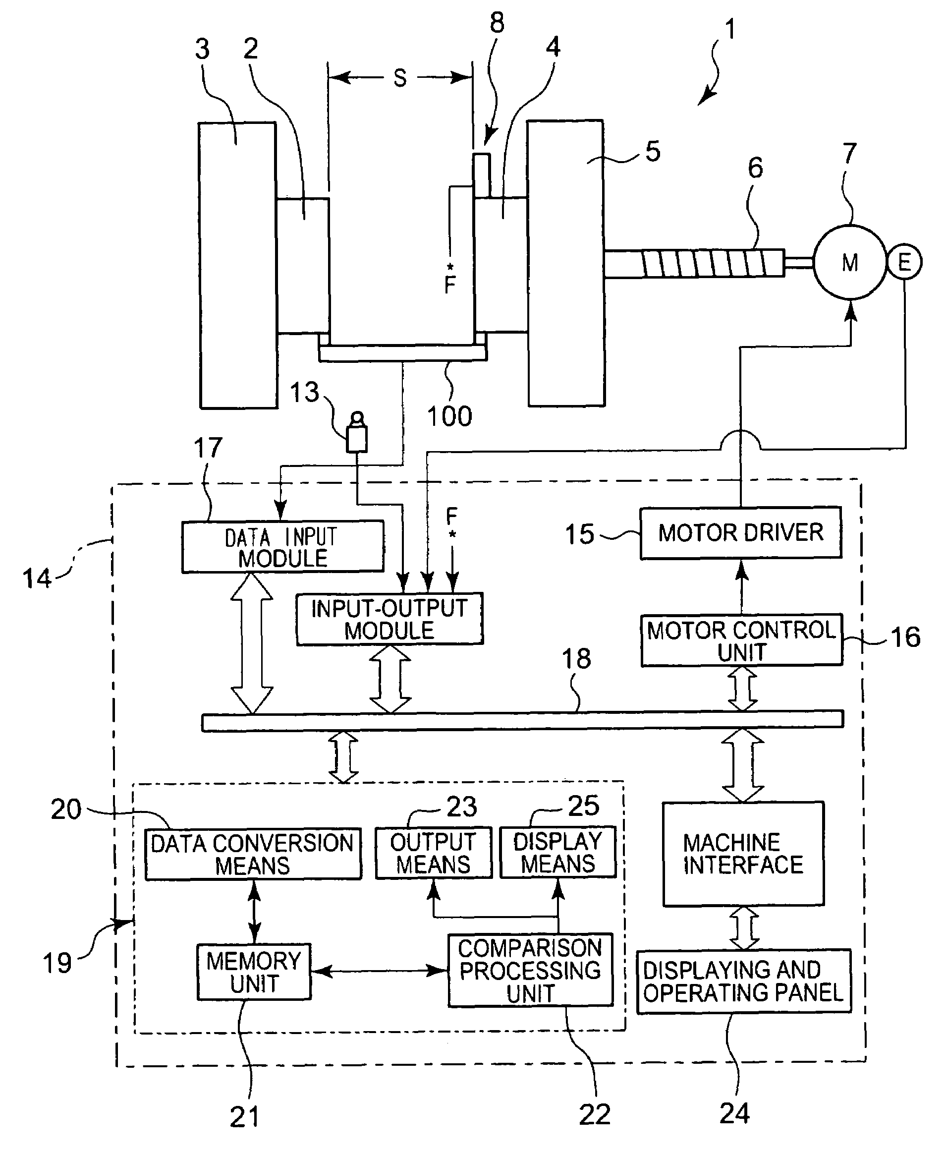
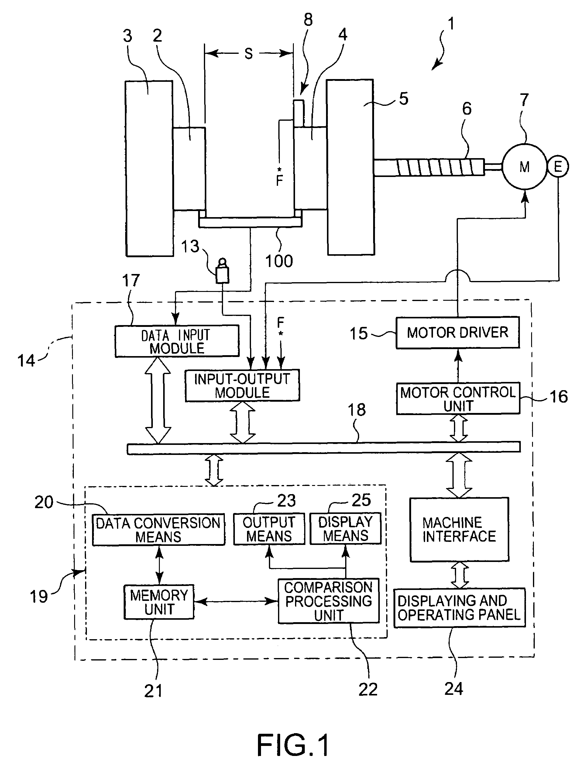
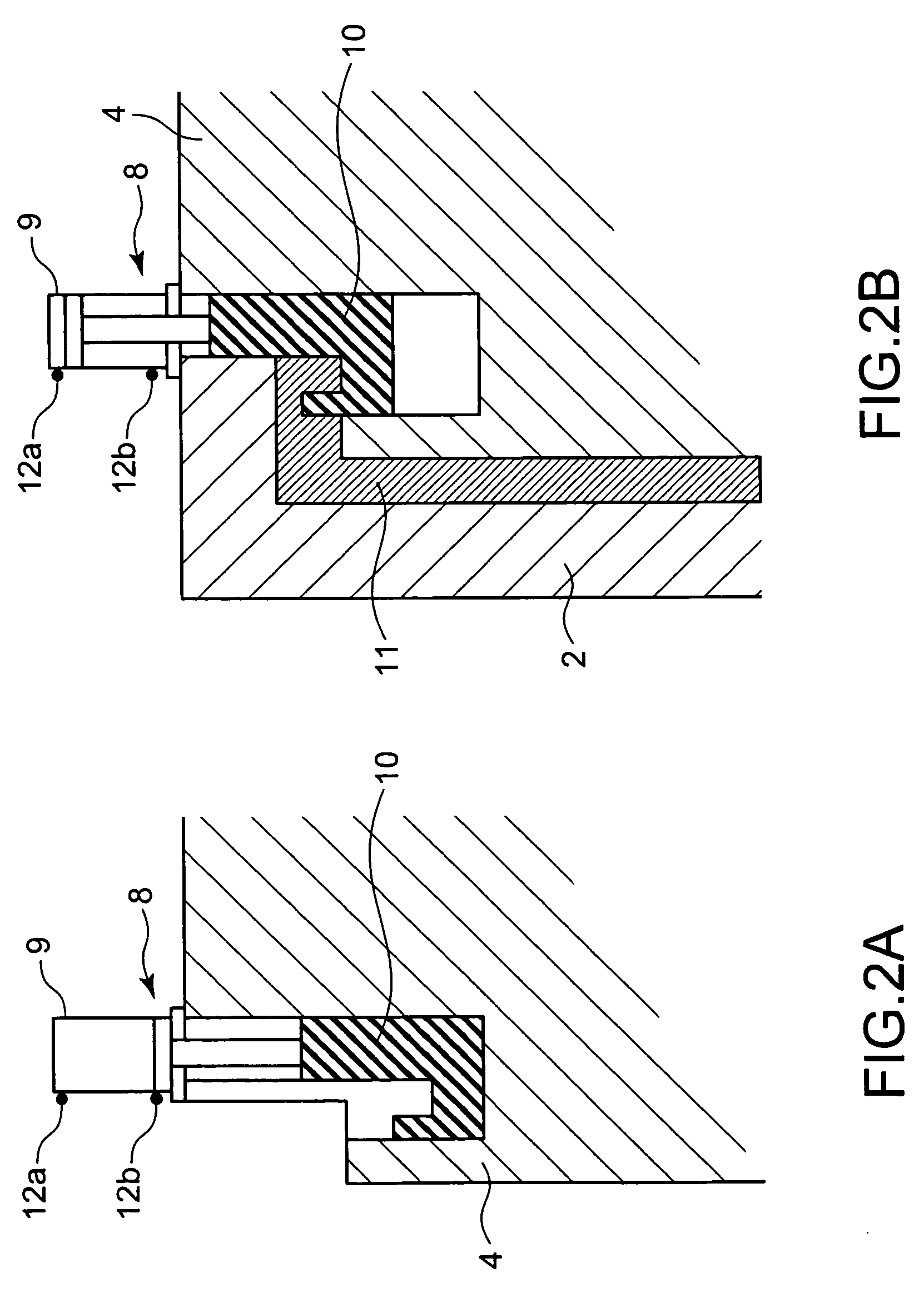
[0019]In FIG. 1, reference numeral 1 denotes an electric clamping unit used in a die casting machine. A fixed mold 2 is attached to a stationary die plate 3, and a movable mold 4 is attached to a movable die plate 5. A cavity 11 is formed between the front mold 2 and the movable mold 4 (see FIG. 2). The clamping unit 1 is driven by a servo-motor 7. The movable die plate 5 to which the movable mold 4 is attached is coupled to a ball screw shaft 6. The ball screw shaft 6 is rotated by the servo-motor 7, and this rotation of the ball screw shaft 6 is converted by a not-shown ball screw mechanism in combination with a ball nut into a linear reciprocation of the movable die plate 5 having a stroke S. In FIG. 1, the movable mold 4 is in a start position of a clamping process, and the stroke S corresponds to a dist...


PUM

PropertyMeasurementUnit
distanceaaaaaaaaaa
travel timeaaaaaaaaaa
timeaaaaaaaaaa

Abstract

Disclosed is a method for electric clamping, which performs a clamping process in parallel with a core-drawing-in process, avoiding damages of molds and core mechanisms and enabling secure clamping. The method comprises the steps of: setting a check point, for judging safety of the clamping process in advance, in a position that is nearer to the operational start position by a predetermined distance in the mold opening direction than a position of the movable mold when the core-drawing-in process is expected to be completed, wherein the core-drawing-in process and the clamping process proceed in parallel with each other in a straight course for reciprocating a movable mold; activating a core system and a servo-motor to start an operation to draw a core into a cavity in parallel with an operation to move the movable mold in the mold closing direction; detecting whether or not the movable mold reaches the check point; judging whether or not the core reaches the position in which the core is fully drawn into the cavity at a point of time at which the movable mold reaches the check point, and confirming the completion of the core-drawing-in process. Thereafter, the clamping process of the molds is further continued if confirming that the core-drawing-in process is already completed.

Description

BACKGROUND OF THE INVENTION[0001]1. Field of the Invention[0002]The present invention relates to a method for electric clamping using a die casting machine, and particularly to a method for electric clamping using a die casting machine equipped with a mold having a core.[0003]2. Background Art[0004]In the past, molding which utilizes a core has been widely used in the field of injection molding machines and die casting machines. In the case of setting a core in a mold, there is an issue on the relation to the clamping process. Conventionally, methods of performing a core-drawing-in process, i.e., a process in which a core is drawn into a mold, before or after the clamping process, or otherwise methods of performing the clamping process in parallel with the core-drawing-in process have been known.[0005]In the former methods, while a safe and secure clamping operation can be provided, the clamping process and the core-drawing-in process must be arranged in series, leading to lengthen ...

Claims


Application Information

Patent Timeline
Patent Type & Authority Patents(United States)
IPC IPC(8): B29C45/80B22D17/32
CPCB22D17/26B29C45/76B29C45/7653B29C45/84B29C2945/76066B29C2945/76869B29C2945/76254B29C2945/76387B29C2945/76575B29C2945/76732B29C2945/76866B29C2945/76083B22D17/22B23P15/24
Inventor ABE, YUJIITANI, SHINYA
Owner TOSHIBA MASCH CO LTD
Why Eureka
Try Eureka