Backlit display with motion sensor

a motion sensor and backlighting technology, applied in the field of displays, can solve the problems of frequent replacement the operating temperature of the backlight unit, and the amount of time it takes for the backlight unit to operate,

Active Publication Date: 2008-07-01
LEGRAND HOME SYST
View PDF354 Cites 90 Cited by
  • Summary
  • Abstract
  • Description
  • Claims
  • Application Information

AI Technical Summary

Problems solved by technology

For example, the rated life of the backlight unit is an important consideration since frequent replacement of the backlight unit, or the light source therein, is costly and time consuming.
Further, design concerns include the amount of time it takes for the backlight unit to begin operation after being turned on, the operating temperature of the backlight unit, the power consumption of the backlight unit, the stability of the brightness of the backlight unit over a temperature range and the amount of electromagnetic interference generated by the backlight unit.
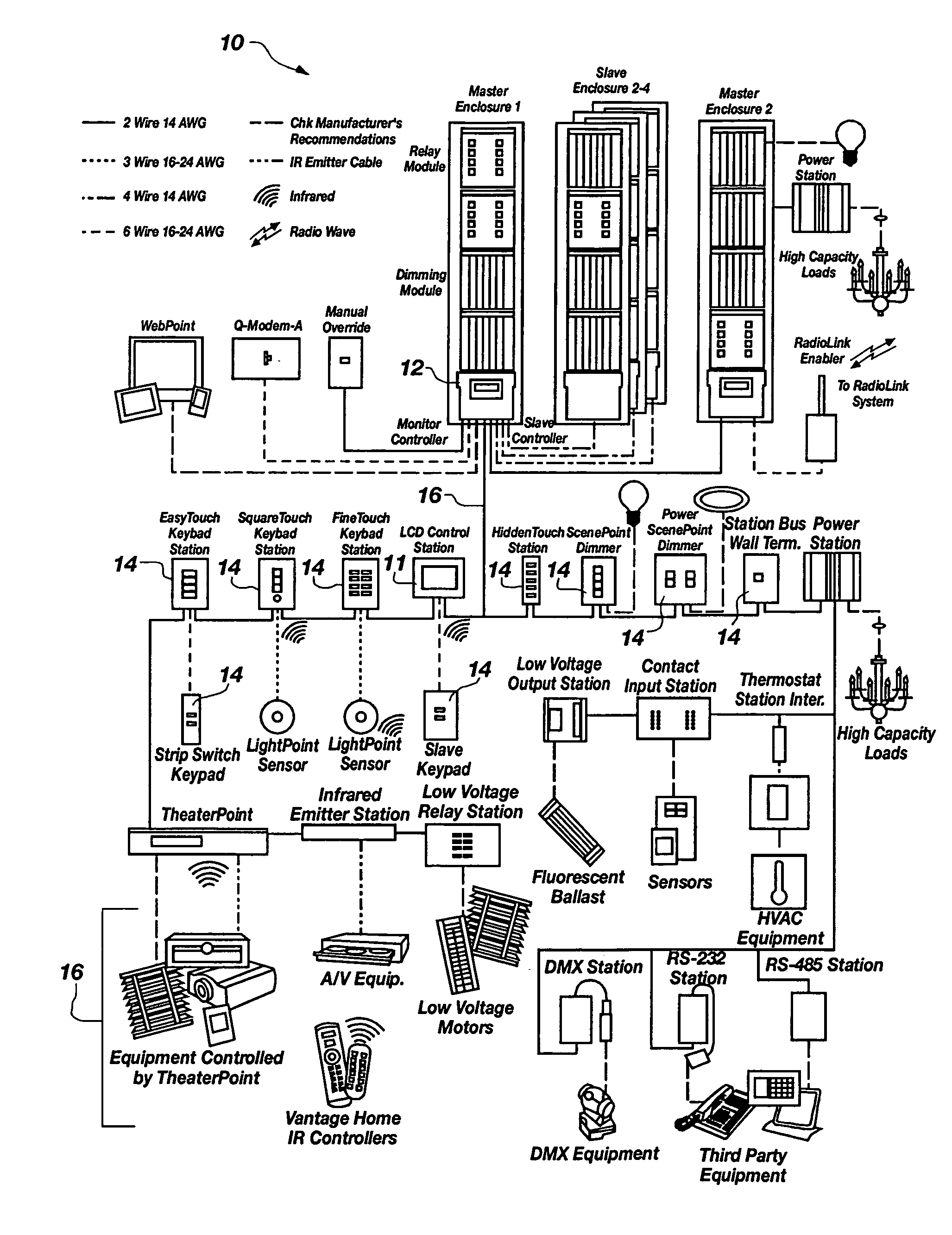
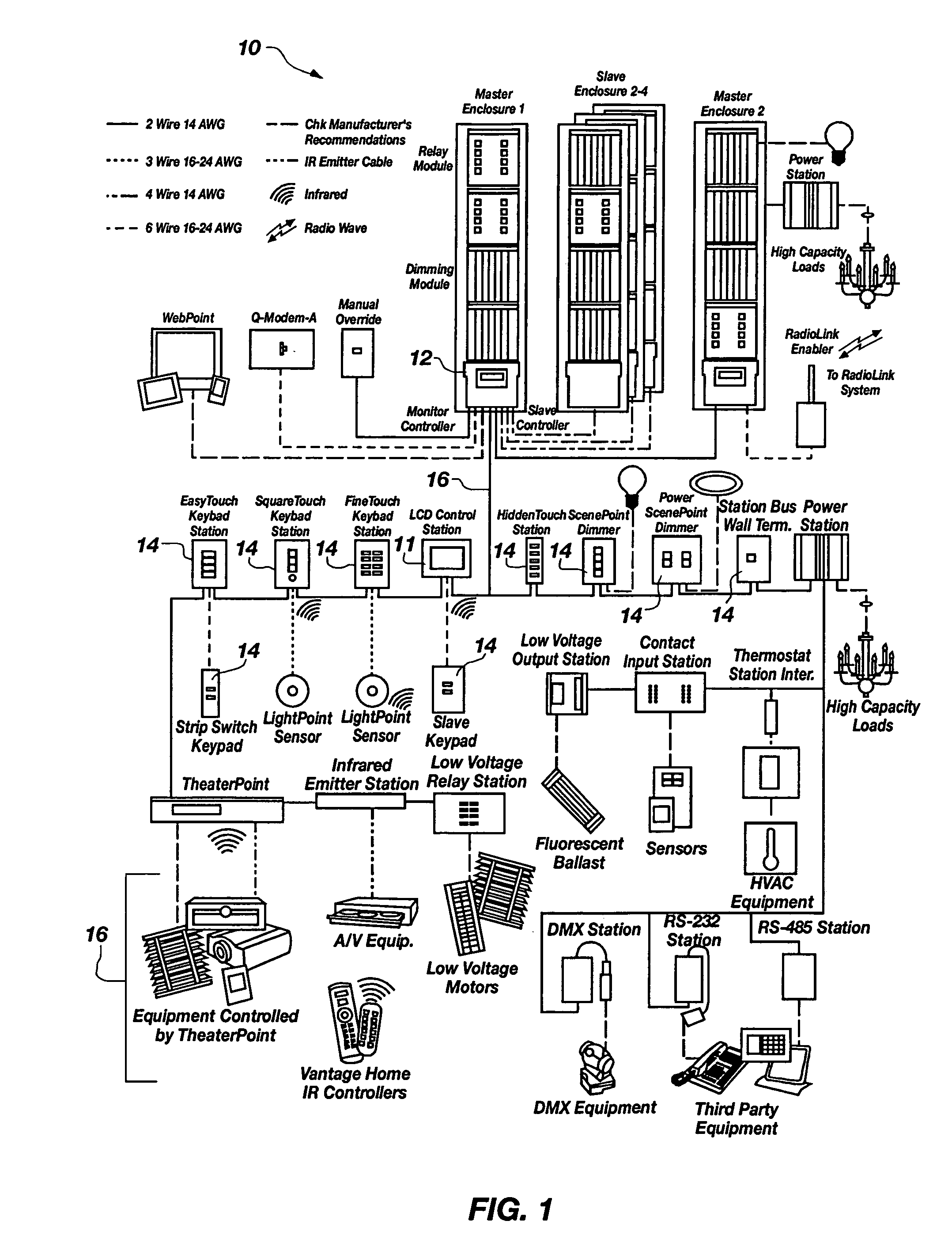
The custom installation world is becoming more and more complex as a mu

Method used


Image

  • Backlit display with motion sensor
  • Backlit display with motion sensor
  • Backlit display with motion sensor

Examples


Embodiment Construction

[0029]For the purposes of promoting an understanding of the principles in accordance with the invention, reference will now be made to the embodiments illustrated in the drawings and specific language will be used to describe the same. It will nevertheless be understood that no limitation of the scope of the invention is thereby intended. Any alterations and further modifications of the inventive features illustrated herein, and any additional applications of the principles of the invention as illustrated herein, which would normally occur to one skilled in the relevant art and having possession of this disclosure, are to be considered within the scope of the invention claimed.

[0030]It must be noted that, as used in this specification and the appended claims, the singular forms “a,”“an,” and “the” include plural referents unless the context clearly dictates otherwise. In describing and claiming the present invention, the following terminology will be used in accordance with the defi...


PUM


Abstract

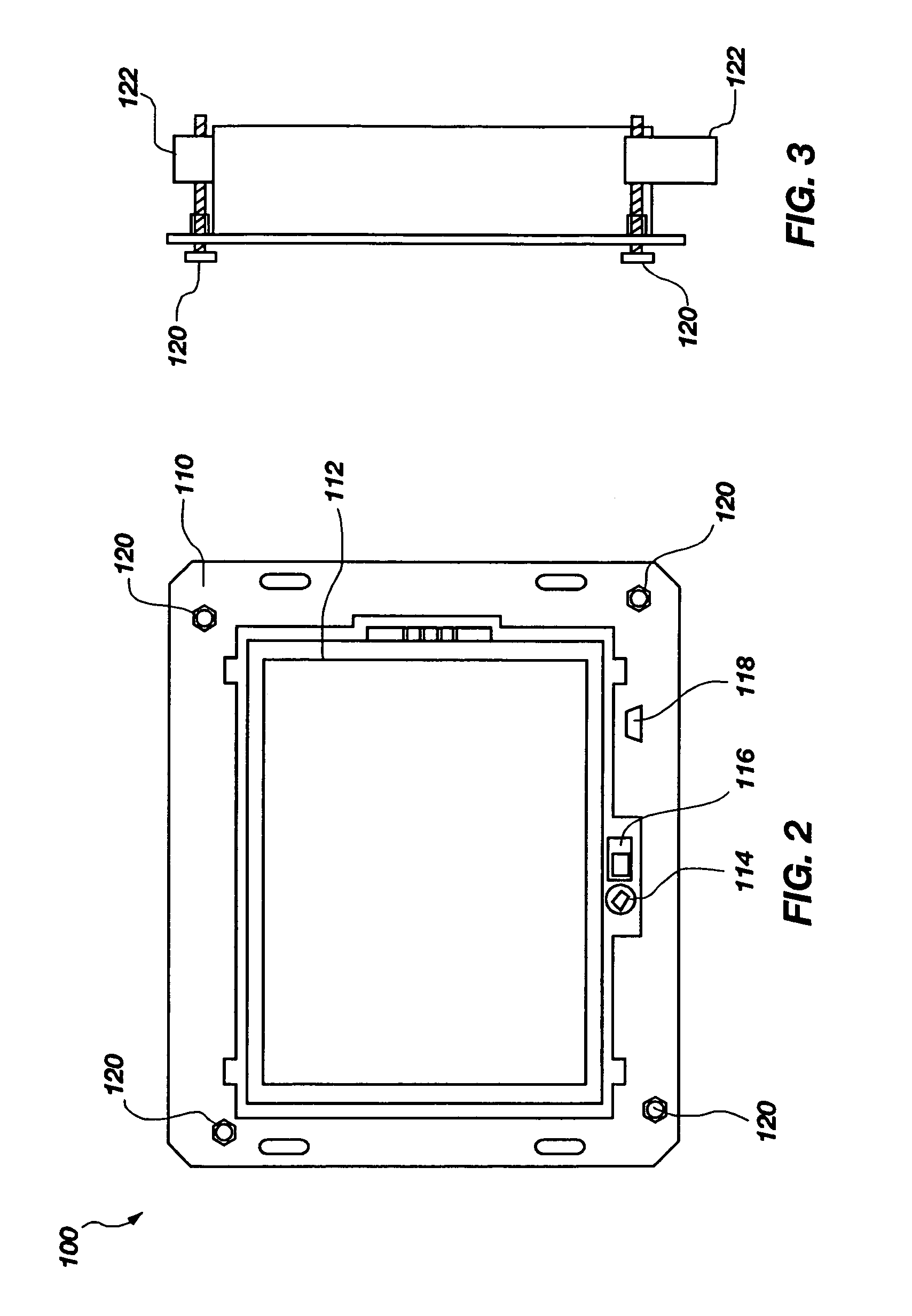
An apparatus for interfacing with a control system, and in particular a home automation system. In one embodiment, the apparatus comprises an integrated LCD touch screen and motion sensor. The motion sensor is used to illuminate a backlight to the touch screen when a person approaches the apparatus. The sensitivity of the motion sensor may be adjusted through a graphical user interface displayed on the touch screen. In addition, the backlighting may be adjusted so that the illumination is at a specific level with the screen is on, i.e., when the motion sensor has been tripped, and a specific level when the screen is off. The apparatus may further comprise an IR receiver for receiving commands via a remote. In addition, the apparatus may be powered from a local bus or an external power supply. The apparatus may comprise a communications port for receiving customized pages from a computer.

Description

CROSS-REFERENCE TO RELATED APPLICATIONS[0001]This application claims the benefit of U.S. Provisional Application No. 60 / 500,146, filed Sep. 3, 2003, which is hereby incorporated by reference herein in its entirety, including but not limited to those portions that specifically appear hereinafter, the incorporation by reference being made with the following exception: In the event that any portion of the above-referenced provisional application is inconsistent with this application, this application supercedes said above-referenced provisional application.STATEMENT REGARDING FEDERALLY SPONSORED RESEARCH OR DEVELOPMENT[0002]Not Applicable.BACKGROUND OF THE INVENTION[0003]1. The Field of the Invention[0004]The present invention relates generally to displays, and more particularly, but not necessarily entirely, to programmable displays for interfacing with control systems.[0005]2. Background Art[0006]Liquid crystal displays (LCDs) are used in a variety of applications, including computer...

Claims


Application Information

Patent Timeline
IPC IPC(8): G09G5/00
CPCG06F1/3203G06F1/3231G06F1/3265G08C17/02G09G3/3406G08C2201/30G08C2201/32Y02B60/1242G09G2320/0261G09G2330/021Y02B60/1289Y10S345/905G08C2201/51Y02D10/00
Inventor PATTEN, DANIELCHANDLER, SCOTT S.CLEGG, PAUL T.MCDANIEL, JOHN
Owner LEGRAND HOME SYST
Why Eureka
Try Eureka