Rotational power servo toolpost

a technology of power servo and toolpost, which is applied in the direction of manufacturing tools, other manufacturing equipment/tools, gear teeth, etc., can solve the problems of limited cutting range and reduced working efficiency, and achieve the effects of increasing working range and cutting methods, reducing working efficiency, and limited cutting rang

Inactive Publication Date: 2008-07-08
KUO CHING HUI
View PDF5 Cites 38 Cited by
  • Summary
  • Abstract
  • Description
  • Claims
  • Application Information

AI Technical Summary

Benefits of technology

[0006]A conventional motor-driven turret includes tool holders fixed thereon. The tool holders move along with the rotated turret to a preset location, but can not spin themselves. Thus the cutting range is limited and the working efficiency is reduced. A primary objective of the present invention is to overcome the disadvantage of the conventional turret. The present invention provides a rotational power servo toolpost that can freely rotate 360 degrees. When the turret of the toolpost rotates to the preset angle, the tool holder within the work area can rotate to a specific working angle, thereby increasing the working range and cutting methods. Therefore, the lathe can be more omni-directional to machine the workpiece, thereby increasing the practicability and convenience.
[0008]When a tool holder moves with the turret into the preset work area, the tool holder and tools can freely rotate, thereby cutting the workpiece from various angles. The cutting range and the cutting methods are increased. The efficiency and the practicability of a lathe equipped with the rotational power servo toolpost according to the present invention are also increased. Because the turret may be provided with a plurality of tool holders having a variety of tools, it is easy to change the needed tool without manually changing tools during the cutting operation. It saves working time and increases an industrial yield.

Problems solved by technology

Thus the cutting range is limited and the working efficiency is reduced.

Method used


Image

  • Rotational power servo toolpost
  • Rotational power servo toolpost
  • Rotational power servo toolpost

Examples


Embodiment Construction

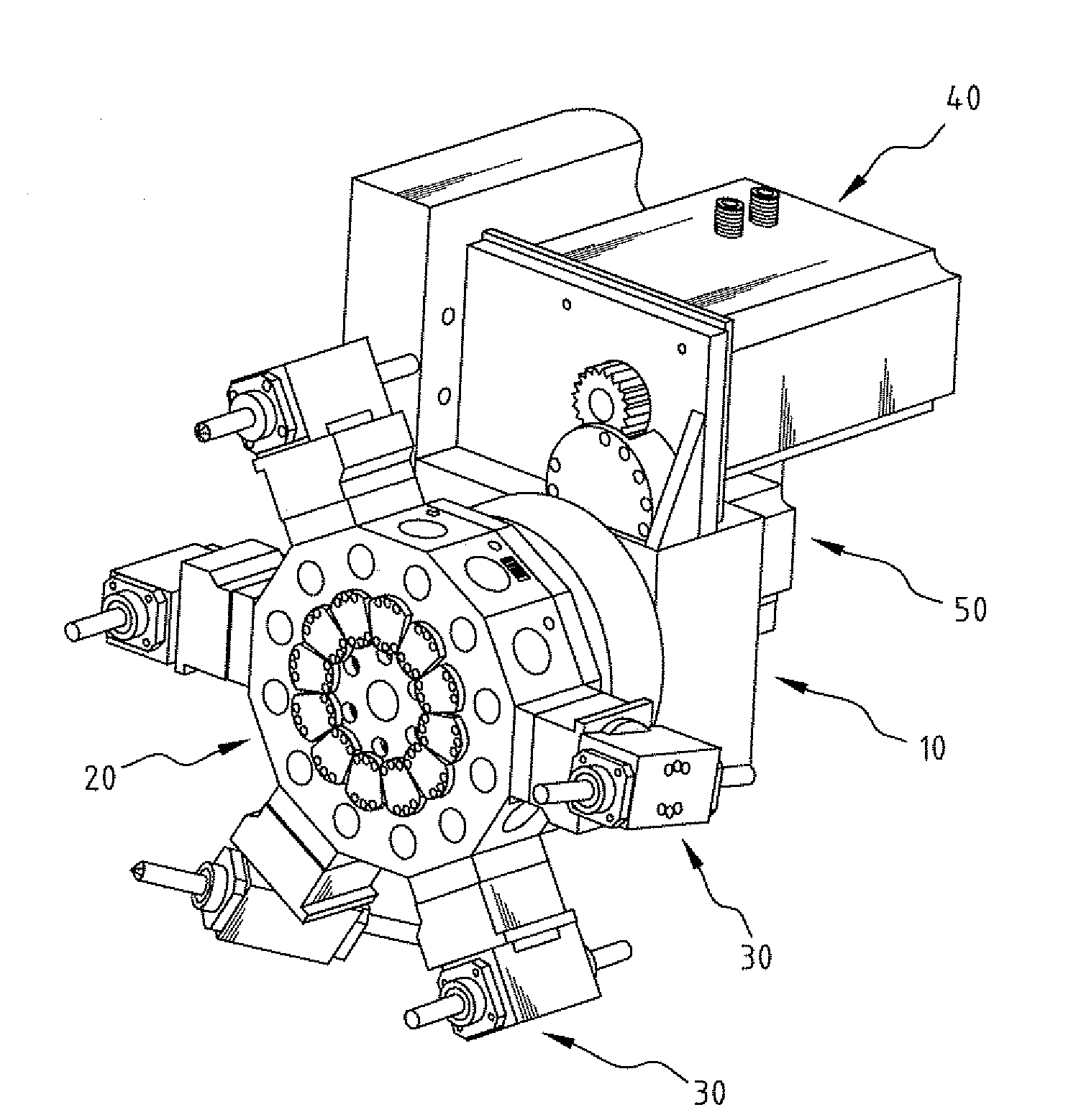
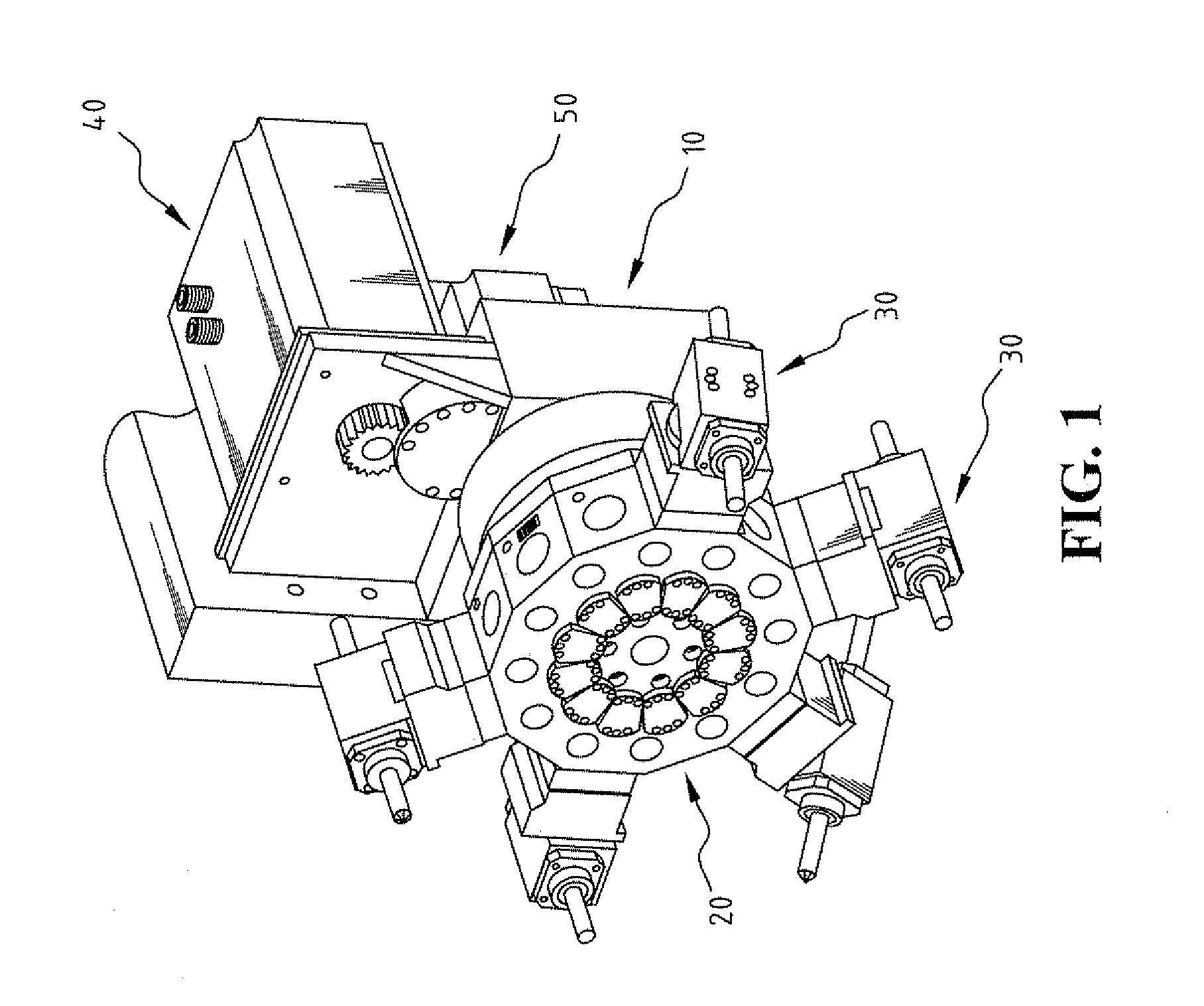
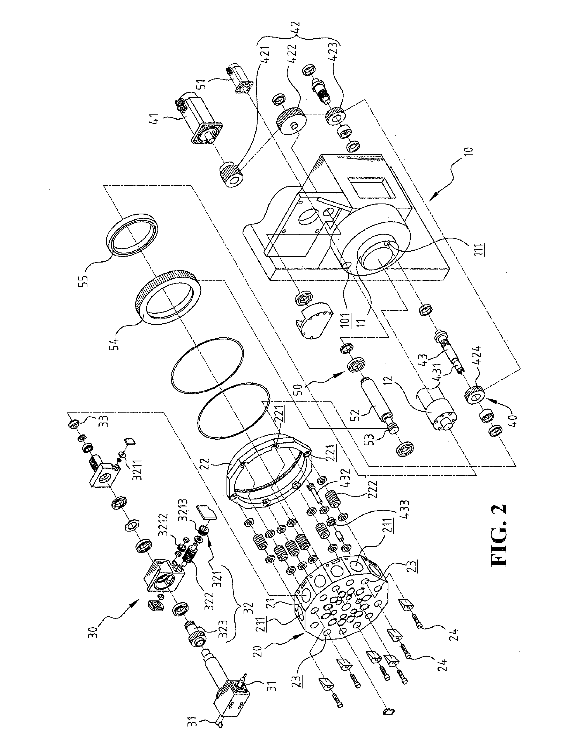
[0013]Referring to FIGS. 1 and 2, a rotational power servo toolpost according to the present invention includes a turret base 10, a turret 20, at least one tool holder 30, a tool-rotating device 40 and a tool-holder-rotating device 50. Each tool holder 30 is mounted on a side surface of the turret 20, and provided with a variety of needed tools 31. Referring to FIG. 3, a tool holder 30 moves with the rotated turret 20 to a preset work area W. A servomotor 51 of the tool-holder-rotating device 50 drives related members to make the tool holder 30 within the work area W to freely rotate 360 degrees. A driving motor 41 of the tool-rotating device 40 drives related members to make the tool 31 of the tool holder 30 to freely rotate 360 degrees, thereby omni-directionally cutting the workpiece.

[0014]The turret base 10 is provided with a protruding joint part 11. One end of a pivot shaft 12 is pivotally connected with the protruding joint part 11, and the other end of the pivot shaft 12 is ...


PUM

PropertyMeasurementUnit
anglesaaaaaaaaaa
areaaaaaaaaaaa
timeaaaaaaaaaa

Abstract

A rotational power servo toolpost includes a plurality of rotational tool holders, which can freely rotate 360 degrees, to cut a workpiece from various angles. The rotational power servo toolpost has a turret base, a turret, tool holders mounted on a side surface of the turret and having a variety of needed tools, a tool-holder-rotating device, and a tool-rotating device. When the tool holder with the needed tool rotates along with the turret to the preset area, a servo motor of the tool-holder-rotating device drives the related members to freely rotate the tool holder around 360 degrees according to the machining requirements. The tool-driving device then drives the tool, thereby cutting the workpiece from various angles.

Description

BACKGROUND OF THE INVENTION[0001]1. Field of the Invention[0002]The present invention relates generally to a toolpost of a lathe, and in particular to a rotational power servo toolpost that includes a plurality of tool holders, which can freely rotate 360 degrees to machine a workpiece from various angles.[0003]2. The Prior Arts[0004]CNC lathe is a powerful machine to perform various operations such as cutting, sanding, or drilling with precision. The CNC lathe uses a variety of cutting tools, such as a lathe tool, a milling cutter, a thread cutter, etc to cut the workpiece, and a computer controller reads instructions and drives the machine tools to fabricate components by the selective removal of metal or other materials.[0005]During machining, a variety of cutting tools cut a workpiece, so it needs to change tools frequently to carry out machining. Therefore, a turret, which includes a plurality of tool holders holding a range of tools and is driven to rotate by a motor, is devel...

Claims


Application Information

Patent Timeline
Patent Type & Authority Patents(United States)
IPC IPC(8): B23B29/32
CPCB23B29/242B23B29/323B23Q5/043B23Q2220/002Y10T82/2587Y10T29/5165Y10T29/5155Y10T409/102385Y10T82/2506Y10T29/5154Y10T29/519Y10T82/2508
Inventor KUO, CHING-HUI
Owner KUO CHING HUI
Why Eureka
Try Eureka