Counter track joint with track turning point

Active Publication Date: 2008-07-08
GKN DRIVELINE INT GMBH
View PDF10 Cites 12 Cited by
  • Summary
  • Abstract
  • Description
  • Claims
  • Application Information

AI Technical Summary

Benefits of technology

[0006]Based on this, it is an object of the present invention, starting from the state of the art mentioned initially, to develop

Problems solved by technology

Counter track joints of this type are disadvantageous in that the angle of articulation is limited to approximately 45 degrees because when this angle of articulation is exceeded, the first ball in the joint arti

Method used


Image

  • Counter track joint with track turning point
  • Counter track joint with track turning point
  • Counter track joint with track turning point

Examples


Embodiment Construction

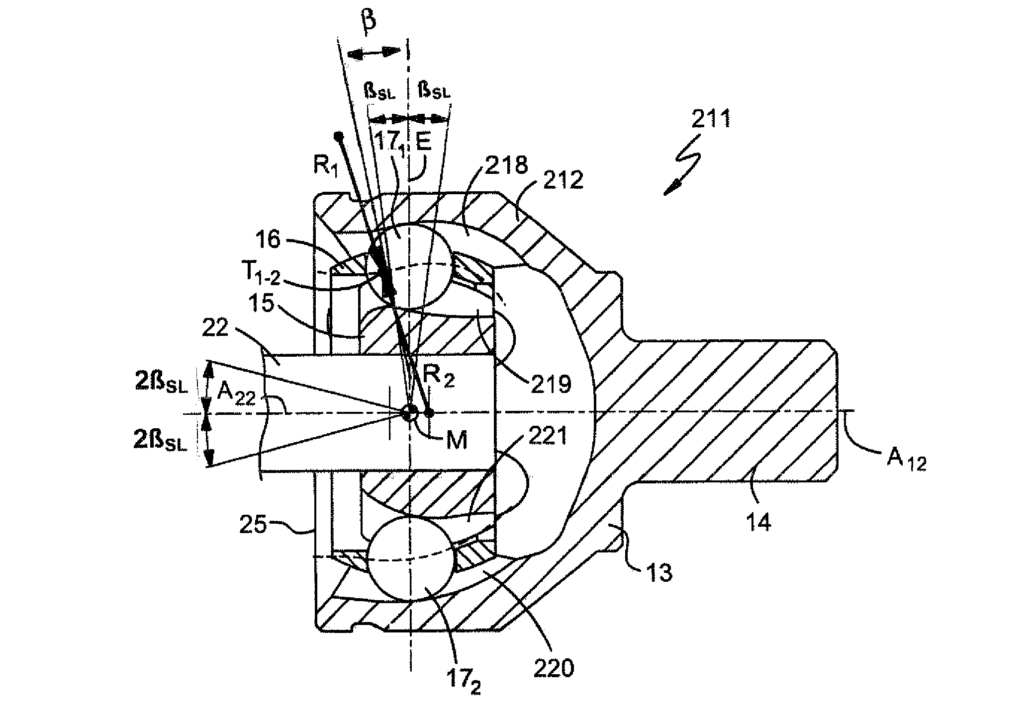
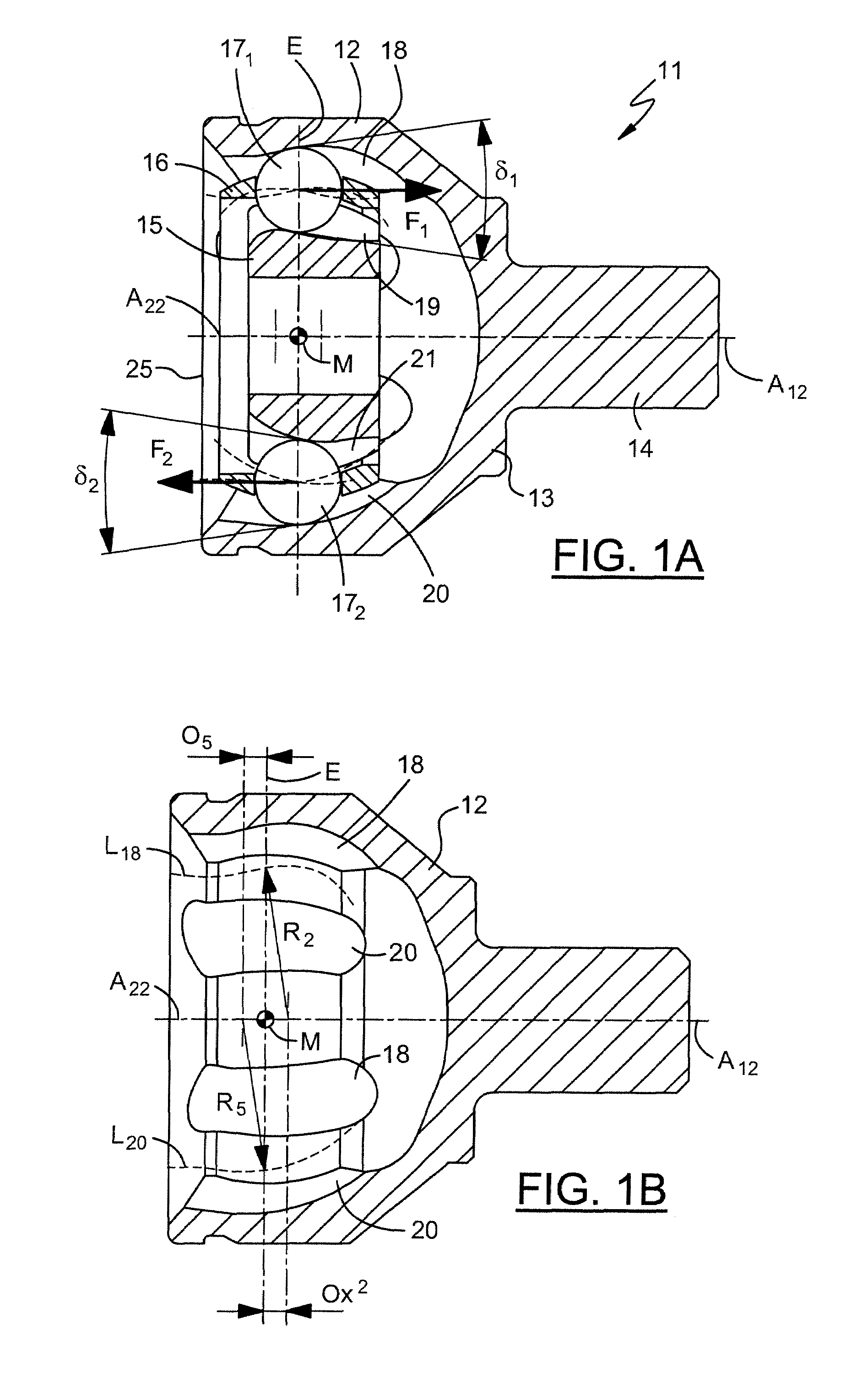
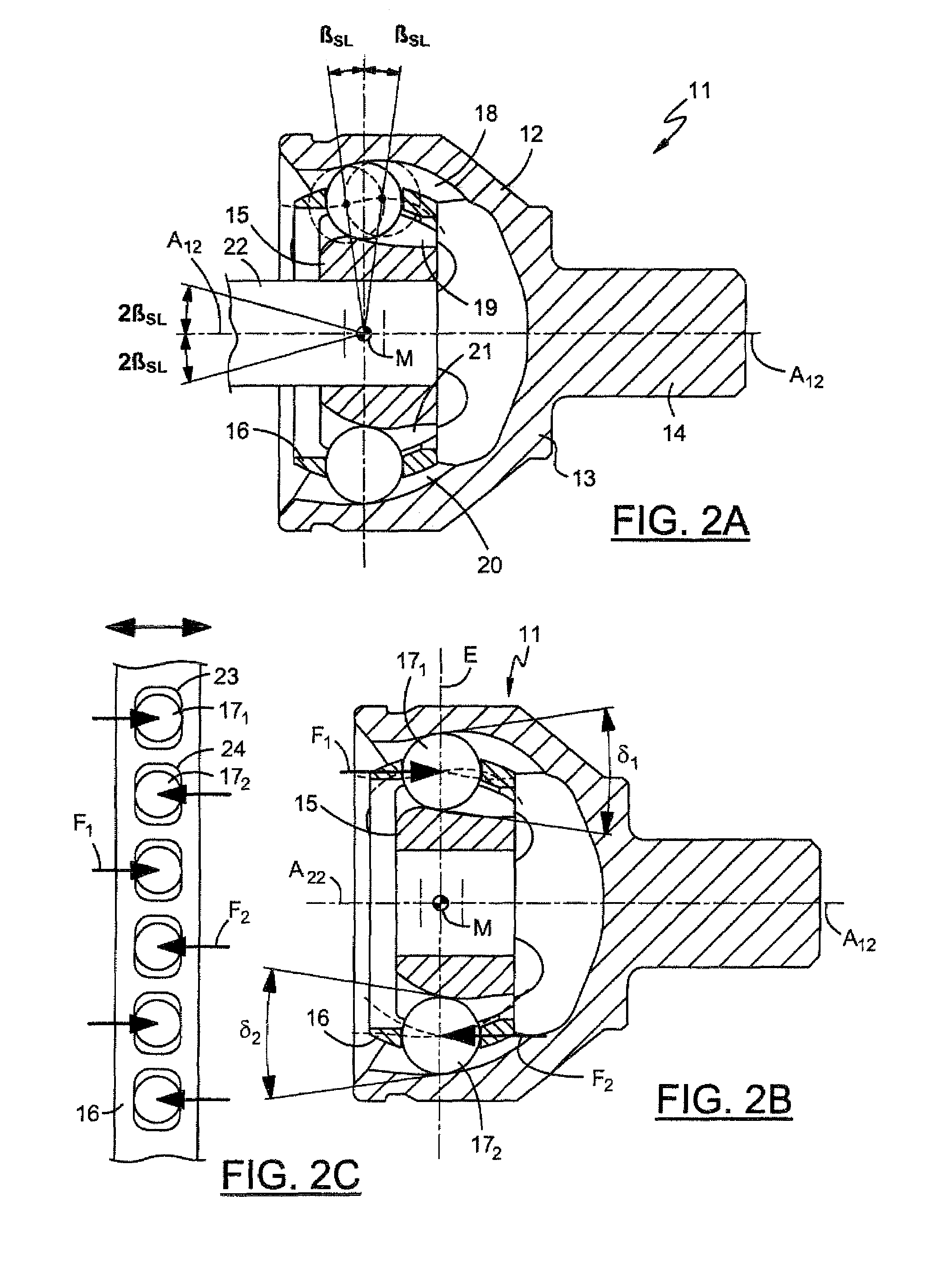
[0039]The two illustrations of FIG. 1 will be described jointly below. An inventive constant velocity joint 11 comprises an outer joint part 12 with an aperture 25 with a closed base 13 and an integrally attached journal 14. Furthermore, the joint comprises an inner joint part 15, a ball cage 16 as well as torque transmitting balls 17. First outer ball tracks 18 and first inner ball tracks 19 accommodate balls 171 and form first pairs of tracks with one another. Second outer ball tracks 20 and second inner ball tracks 21 form second pairs of tracks which receive second balls 172. The two types of pairs of tracks are alternately arranged around the circumference. Tangents at the balls in the points of contact with the first pairs of tracks which are shown in the drawing, together, form an opening angle δ1 which opens in the direction towards the base 13. Tangents at the second balls 172 in the points of contact with the second pairs of tracks, together, from an opening angle δ2 which...


PUM

PropertyMeasurementUnit
Angleaaaaaaaaaa
Angleaaaaaaaaaa
Angleaaaaaaaaaa

Abstract

A constant velocity counter track joint (11) having an outer joint part with first outer ball tracks (18) and second outer ball tracks (20), an inner joint part with first inner ball tracks (19) and second inner ball tracks (21). A ball cage (16) is positioned between the outer joint part and the inner joint part with cage windows which each accommodate at least one of the balls. When the joint is in the aligned condition, the aperture angle (δ1) of the pairs of first tracks opens in the central joint plane (E) from the aperture end to the attaching end of the outer joint part (12), and the aperture angle (δ2) of the pairs of second tracks opens in the opposite direction. The central track lines (L18, L19) of the first pairs of tracks each have a turning point (T1-2), and the center angle (β) from the joint center to the turning point (T1-2), is greater than 4°.

Description

TECHNICAL FIELD[0001]The invention relates to a constant velocity joint in the form of a counter track joint with the following characteristics: an outer joint part which comprises a first longitudinal axis and an attaching end and an aperture end which are axially opposed relative to one another, and which outer joint part further comprises first outer ball tracks and second outer ball tracks; an inner joint part which comprises a second longitudinal axis and attaching means for a shaft pointing to the aperture end of the outer joint part, and which inner joint part further comprises first inner ball tracks and second inner ball tracks; the first outer ball tracks and the first inner ball tracks form first pairs of tracks with one another; the second outer ball tracks and the second inner ball tracks form second pairs of tracks with one another; the pairs of tracks each accommodate a torque transmitting ball; a cage is positioned between the outer joint part and the inner joint par...

Claims


Application Information

Patent Timeline
IPC IPC(8): F16D3/224C03C17/00C03C17/245C03C17/34C03C17/42C04B41/52C04B41/89C23C16/40C23C16/453C23C26/00C23C28/00F16D3/223
CPCC04B41/009C04B41/52C04B41/89F16D3/065F16D3/2233F16D3/224C04B41/4537C04B41/5035C04B41/5041C04B41/0072C04B41/4543C04B41/455C04B41/4933C04B41/5089C04B33/00C04B2111/2069F16D2003/22303F16D2003/22306Y10S464/906
Inventor WECKERLING, THOMAS
Owner GKN DRIVELINE INT GMBH
Why Eureka
Try Eureka