Lignocellulose fiber-resin composite material

a technology of lignocellulose fiber and resin, which is applied in the field of lignocellulose fiberresin composite materials, can solve the problems of slow and difficult roll installation and removal, excessive weight and high erection cost, and achieve the effects of improving skin formation, reducing production costs, and improving process efficiency

Inactive Publication Date: 2008-07-08
TEMBEC INC
View PDF13 Cites 16 Cited by
  • Summary
  • Abstract
  • Description
  • Claims
  • Application Information

AI Technical Summary

Benefits of technology

[0009]We have found that by reducing the degree of fissures, voids and the like, i.e. flaws, in a dried lignocellulose fiber material of a thickness of at least 5 mm, preferably of at least 2 cm, that a useful product can be obtained according to the invention.
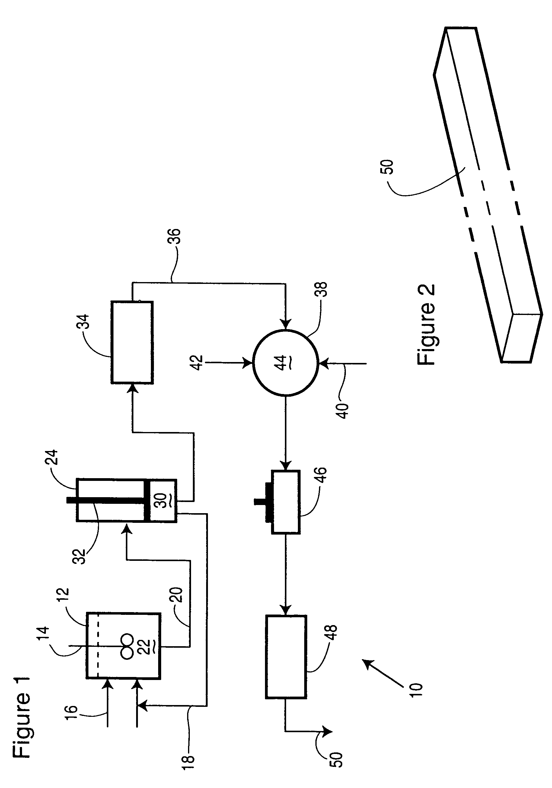
[0040]The formed, impregnated material is then, preferably, placed in a curing oven at a temperature, generally of about 50-95° C., for 4-24 hours in order to completely cure the resin. The initial curing temperature must be kept, most preferably, below 100° C. because of the thickness of the formed material being cured, and because water is released from the resin during the curing process. At the beginning of the curing process, the resin at the outer surface is the first to cure and form an impermeable layer. Subsequently, the resin in the interior of the form begins to cure after this outer layer has been formed. If water is trapped within the form and goes beyond 100° C., it will boil, create pressure, and the sealed form will rupture before the moisture has time to escape via natural permeation. The curing temperature can be increased beyond 100° C. later in the cure to maximize polymerization and thus, strength.

Problems solved by technology

However, frequently, the limitations of steel, which include corrosion and maintenance challenges, excessive weight and high erection costs are being recognized.
As an example, in bridge construction it is estimated that within the next 25 years, over 50% of all of the bridges in North America will either require extensive repair or complete replacement due to the lack of sustained infrastructure funding.
This extreme weight accelerates bearing failure, and results in slow and difficult roll installation and removal.

Method used


Image

  • Lignocellulose fiber-resin composite material

Examples


example 1

[0052]As a starting material, 140 grams of bleached paper grade sulfite pulp was mixed with 50° C. water in a British Disintegrator to produce a slurry with a consistency of 2.5%. The slurry was then poured into a perforated formation trough and the trough topped up with water. Without external pressure, there is only minimal water loss. The slurry in the trough was mixed again to ensure good randomization. The plunger was set in place and forced downward by hand to begin the dewatering step. Once the end of the plunger shaft had descended enough, the slurry was compressed under a screw mechanism to attain a dry bulk density of 0.45 g / cm3. The bottom plate was removed and the wet fiber form in the shape of a rectangular brick of length 20 cm, width 10 cm and thickness 5 cm, was pushed out the bottom and placed in an oven at 85° C. for 8 hours to dry.

[0053]The dry brick was cut into 6 pieces, four of them were labeled 3A, 3B, 3C, 3D and their weights measured. One at a time, each pie...

example 2

[0060]Using the same preparation as in Example 1, two fiber bricks of differing densities (series 2 fiber density: 0.53 m / cm3, series 1 fiber density: 0.46 g / cm3) were produced, segmented, impregnated with resin TXIM 383 and the impregnated pieces cured. The difference with these sets was that higher pressures were attempted. Table 2 lists the results.

[0061]

TABLE 2Final BonePressureTimeInitial Air DryDry CompositeSample ID(psi)(min)Pulp Wt (g)Wt (g)Visual Inspection2C90-1002.520.745.2Slight non-impregnatedcore2A90-1005.022.649.0Fully impregnated2B1107.520.451.5Fully impregnated2D90-10010.023.849.3Fully impregnated1A1000.522.943.3Large non-impregnatedcore1B1001.021.248.1Slight non-impregnatedcore1C1001.519.650.8Fully impregnated1D1002.021.951.1Fully impregnated

[0062]A summary of the observations is as follows:

[0063]During impregnation, there appeared to be minimal fiber swelling.

[0064]All of series 2 were almost completely impregnated. This indicates that less impregnation time is re...

example 3

[0066]Using the same preparation as in Example 1, three other phenol formaldehyde resin formulations were tested in order to observe any differences during impregnation and curing. Samples from all three previous fiber shape series were used under two impregnation pressure and time conditions. The resin viscosities are listed below along with the impregnation temperature. Table 3 describes the results.

[0067]TDIM 387: viscosity 252 cps@ 25C

[0068]TXIM 389: viscosity 148 cps @ 25C

[0069]TXIM 391: viscosity 272 cps @ 25C

[0070]Impregnation temp: 21C.

[0071]

TABLE 3InitialFinalWeightSamplePressureTimeAD PulpBD wtIncreaseResin CodeID(psi)(min)Weight (g)(g)(%)TXIM 3871E15419.729.433TXIM 3892E15420.332.058TXIM 3913E15421.432.050TXIM 3871F30224.135.949TXIM 3892F30224.741.668TXIM 3913F30225.638.651

[0072]The results are as follows:

[0073]The lower viscosity TXIM 389 impregnated much faster, but the percentage of lower molecular weight material seems to be higher (i.e. larger brown region). This may...


PUM

PropertyMeasurementUnit
thicknessaaaaaaaaaa
lengthaaaaaaaaaa
lengthaaaaaaaaaa

Abstract

A method of making a formed, dried lignocellulose fiber material comprising (a) providing an aqueous lignocellulose fiber pulp slurry having an effective consistency; (b) de-watering the slurry to provide a de-watered material at an effective de-watering rate under an effective pressure to prevent or reduce the formation of fissures and voids within the material; (c) drying an effective amount of the de-watered material at an effective temperature and period of time to provide the formed, dried lignocellulose fiber material having a thickness of at least 5 mm. The formed, dried lignocellulose material may be used to make a lignocellulose fiber-resin composite material of use as a cost effective structural member, as a substitute for steel, in, for example, bridges, processing equipment, and the like.

Description

FIELD OF THE INVENTION[0001]This invention relates to lignocellulose fiber-resin composite materials, particularly with thermoset resins; dried lignocellulose fiber used in the manufacture of said composite materials and apparatus and processes in the manufacture thereof.BACKGROUND TO THE INVENTION[0002]Presently, carbon steel is the material of choice for most exterior infrastructure applications because of its superior strength properties and relatively low cost per unit weight. However, frequently, the limitations of steel, which include corrosion and maintenance challenges, excessive weight and high erection costs are being recognized. As an example, in bridge construction it is estimated that within the next 25 years, over 50% of all of the bridges in North America will either require extensive repair or complete replacement due to the lack of sustained infrastructure funding. Most of the major civil engineering and government authorities have expressed their lack of enthusiasm...

Claims


Application Information

Patent Timeline
Patent Type & Authority Patents(United States)
IPC IPC(8): D21F13/00D21J1/00D21J1/04D21J1/06D21J1/08D21J1/12
CPCD21J1/00D21J1/08Y10T428/24455Y10T428/23957
Inventor SCOBIE, MICHAEL A. N.
Owner TEMBEC INC
Why Eureka
Try Eureka