
Light sensor module, focused light sensor array, and an air vehicle so equipped

a technology of light sensor array and light sensor module, which is applied in the direction of instruments, instruments for comonautical navigation, distance measurement, etc., can solve the problem that sensors are not readily suited for deploymen

Active Publication Date: 2008-07-08
NORTHROP GRUMMAN SYST CORP
View PDF9 Cites 53 Cited by
  • Summary
  • Abstract
  • Description
  • Claims
  • Application Information

AI Technical Summary

Benefits of technology

[0004]In some light-sensing module embodiments, the mounting support structure may be an optical bench. In some light-sensing module embodiments, the optical element may be an aspheric, complex mirror, or a lens. Embodiments of the invention include arrays comprised of a plurality of light-sensing modules mounted in or about a mounting structure that may include guidance section housings of an air vehicle such as a missile or projectile. The incident detections along with their associated times-of-arrival, as individual light-sensing module outputs, may be provided to a signal processor adapted to correlate or otherwise integrate the outputs of the plurality of light-sensing modules. The signal processor may be part of the guidance processing of an air vehicle such as a missile or projectile where information extracted from incident coherent light pulses reflected from one or more designated targets including their pixel location and associated time-of-arrival (TOA) or time-of-measurement (TOM) as represented by their time tag, for example, and their derived angles-of-arrival relative to the air vehicle may be output from the signal processing subsystem of a module to a guidance processing subsystem or module, all of which may be housed within a guidance section.

Problems solved by technology

In applications where the support structure geometry, or the economies of multi-sensor suites, precludes or otherwise forecloses particular surface areas or volumes for mounting specific electromagnetic sensors, these sensors are not readily suited for deployment in a distributed fashion about a portion or portions of the mounting structure having one or more prominences that obstruct what would otherwise be an unobstructed field-of-view (FOV).

Method used


Image

  • Light sensor module, focused light sensor array, and an air vehicle so equipped
  • Light sensor module, focused light sensor array, and an air vehicle so equipped
  • Light sensor module, focused light sensor array, and an air vehicle so equipped

Examples


Embodiment Construction

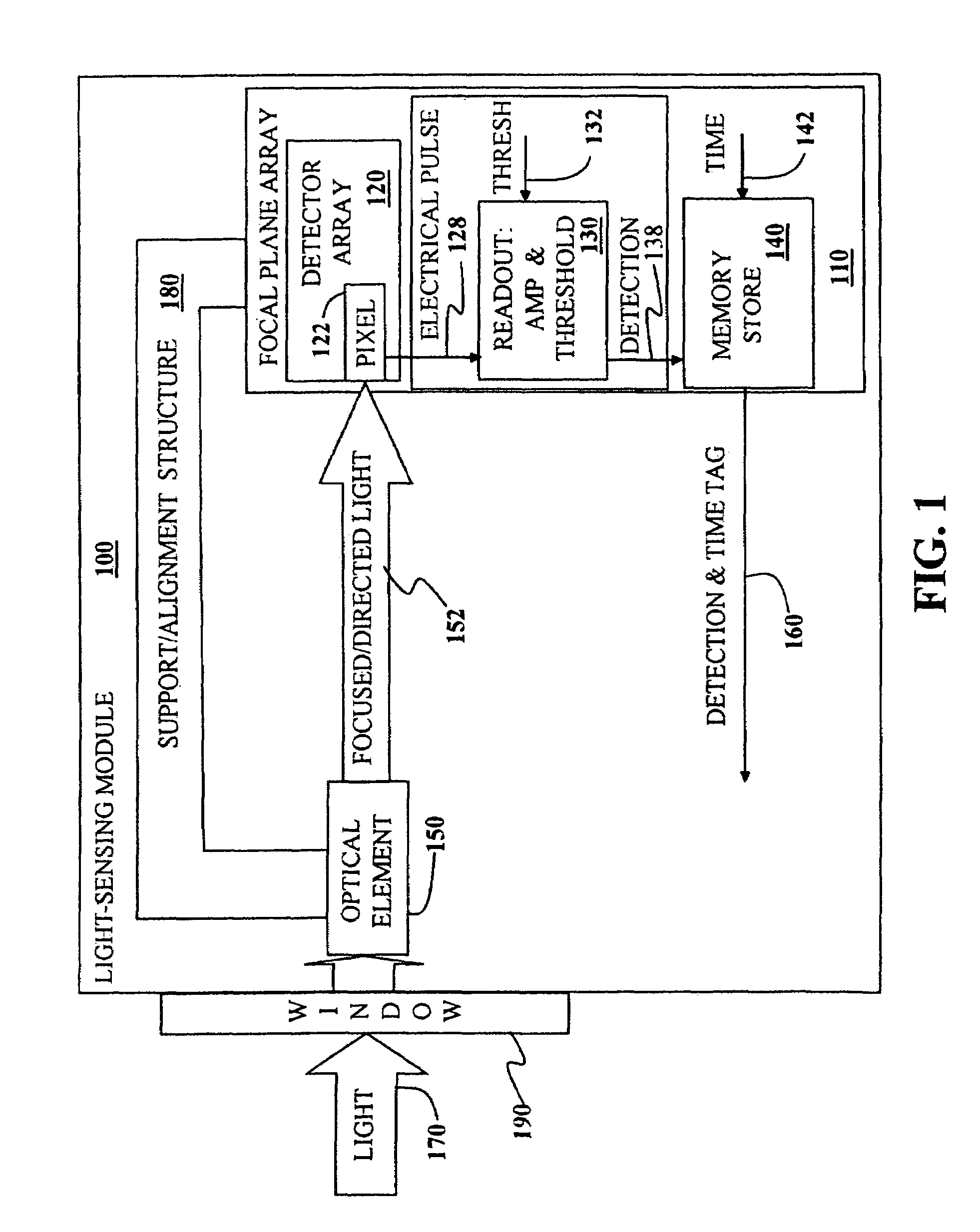
[0024]The several embodiments of the present invention, as illustrated in FIG. 1, include one or more light-sensing devices 100, each light-sensing device 100 having a focal plane array (FPA) 110 and where each light-sensing device 100 provides a time-tagged or time-associated detection output 160. The light-sensing device 100 further includes an optical element 150, such as a lens, a mirror, or both, to focus and / or direct incoming light 170 or an incoming light signal to one or more pixel-related regions 122 of the FPA 110. The FPA 110 may further include a detector array 120, a readout 130 which may include amplifying and thresholding circuitry, and a memory store 140. The threshold values 132 may be set external from the readout 130. The amplifying and thresholding circuitry 130 may also include multiplexing circuitry and may be part of a readout integrated circuit (ROIC). An exemplary response of the detector array 120 to an incident light pulse is a photoelectrical response ca...


PUM


Abstract

A light-sensing module and arrays of two or more light-sensing modules are described. Each light-sensing module comprises a mounting support structure that may include an air vehicle guidance section and an optical element adapted to direct incident light to a detector array that comprises an array of photodiodes and is attached to the mounting support structure. The detector array is adapted to receive the directed light and convert the received light to a set of electrical pulses via a plurality of photodetectors each of which is operatively coupled to an amplifier and a threshold circuit adapted to output a detection to a memory store adapted to associate a detection with a time-of-arrival. The light-sensing module may be adapted to output the associated detection and time-of-arrival. Air vehicles including the light-sensing modules are also disclosed.

Description

BACKGROUND[0001]The present invention, in several embodiments, relates to light-sensing modules and, more particularly, to arrays of light-sensing modules adapted to have overlapping fields-of-view with each module having a focal plane array and processing structure to receive focused incident optical energy and output detection locations, each detection location being associated with a time tag or time-of-detection. An air vehicle equipped with at least one light-sensing module is also encompassed by the present invention.[0002]Sensors of electromagnetic energy and signals are typically mounted to a support structure either for stability, conveyance or both. In applications where the electromagnetic signals of interest are of wavelengths best measured by two or more sensors, a distributed array of sensor elements, e.g., antenna elements, are typically employed. In applications where the electromagnetic signals to be received by the sensor are small in wavelength relative to the mou...

Claims


Application Information

Patent Timeline
Patent Type & Authority Patents(United States)
IPC IPC(8): G01C21/02G01C3/08
CPCG01S3/784F41G7/2293F41G7/226
Inventor BYARS, JAMES E.KISSEL, STEPHEN JOSEPHRINGDAHL, JOHN J.
Owner NORTHROP GRUMMAN SYST CORP
Features
  • Generate Ideas
  • Intellectual Property
  • Life Sciences
  • Materials
  • Tech Scout
  • Unparalleled Data Quality
  • Higher Quality Content
  • 60% Fewer Hallucinations
Learn More