Write burst stop function in low power DDR sDRAM
- Summary
- Abstract
- Description
- Claims
- Application Information
AI Technical Summary
Problems solved by technology
Method used
Image
Examples
Embodiment Construction
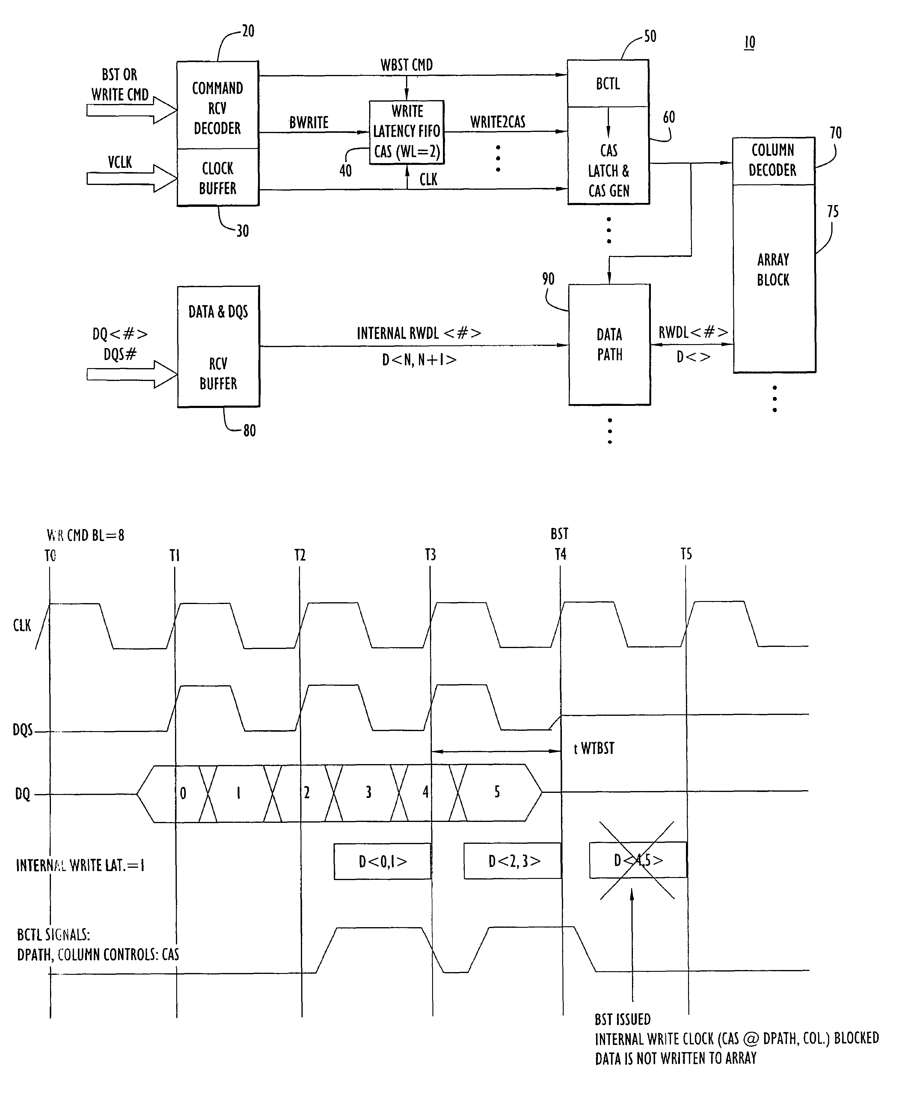
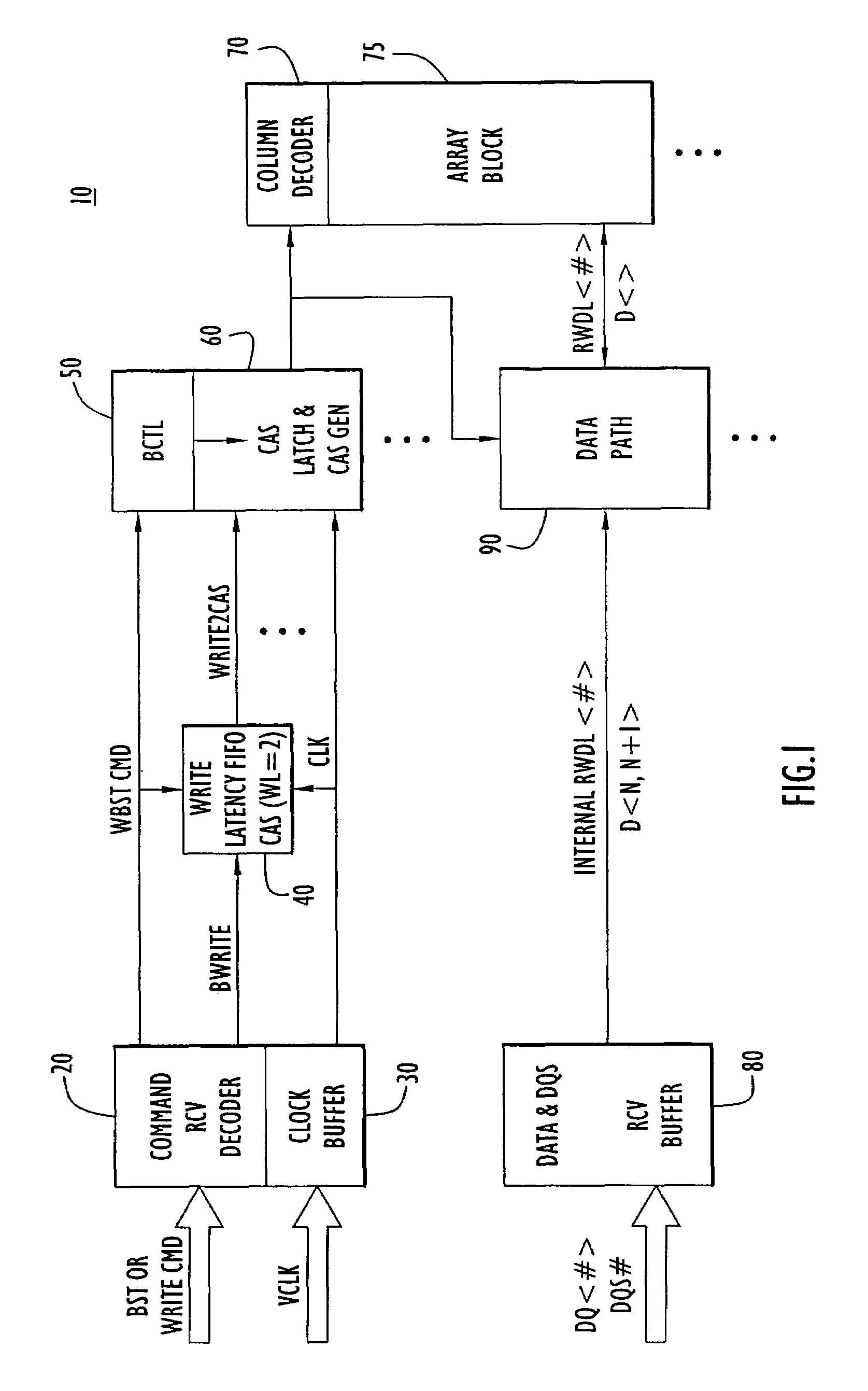
[0011]Referring first to FIG. 1, the circuitry in a semiconductor memory device 10 that is relevant to the write burst stop function is shown. There is a command receive decoder 20 that receives command signals from a host device (not shown) including, in particular, a write command (WRITE CMD) signal and a burst stop command (BST) signal. There is also a clock buffer circuit 30 that receives a clock signal (VCLK) supplied by the host device. The command receive decoder 20 is connected to a write latency first-in first-out (FIFO) circuit 40 and to a burst control circuit (BCTL) 50. The clock buffer 30 is also connected to the write latency FIFO 40 and to a column address strobe (CAS) latch and CAS generator circuit 60. The CAS latch and CAS generator circuit 60 is connected to a column decoder 70 and memory cell array 75 for a memory bank. The memory device 10 may have multiple memory banks and the circuits 40 and 60 are repeated for the memory array of each bank.
[0012]Data received...
PUM
 Abstract
Description
Claims
Application Information
 - R&D
- Intellectual Property
- Life Sciences
- Materials
- Tech Scout
- Unparalleled Data Quality
- Higher Quality Content
- 60% Fewer Hallucinations
Browse by: Latest US Patents, China's latest patents, Technical Efficacy Thesaurus, Application Domain, Technology Topic, Popular Technical Reports.
© 2025 PatSnap. All rights reserved.Legal|Privacy policy|Modern Slavery Act Transparency Statement|Sitemap|About US| Contact US: help@patsnap.com


