
Synchronous signal processing system

a signal processing and synchronization technology, applied in the field of synchronization signal processing system, can solve the problems of complicated system design for synchronization and complicate the development of a new product for the system

Inactive Publication Date: 2004-07-13
RENESAS ELECTRONICS CORP
View PDF16 Cites 2 Cited by
  • Summary
  • Abstract
  • Description
  • Claims
  • Application Information

AI Technical Summary

Benefits of technology

The present invention relates to a signal processing system that can handle multiple processors operating with different clock signals as a synchronous system operating with a single clock signal. This is achieved without using a clock exchanger, which simplifies circuit design and reduces circuit scale. The system includes a PLL circuit for generating a system clock signal and a set of external interfaces and a user data logic block for receiving and transmitting data. The data path circuit uses the system clock signal for data processing, while the CPU uses a separate clock signal for processing data. The system can be designed using techniques described in previous patents. The technical effect of the invention is to simplify circuit design and reduce circuit scale of the signal processing system.

Problems solved by technology

Thus, if a plurality of CPUs or processors are disposed in a single system, the design for synchronization is difficult in the system.
There is a disadvantage in the conventional signal processing system in that the presence of the clock exchanger 18 increases the circuit scale of the UDL block 14 and thus the circuit scale of the entire system.
In addition, the asynchronous configuration of the signal processing system complicates development of a new product for the system during the circuit design and simulation thereof.

Method used


Image

  • Synchronous signal processing system
  • Synchronous signal processing system
  • Synchronous signal processing system

Examples


Embodiment Construction

Now, the present invention is more specifically described with reference to accompanying drawings, wherein similar constituent elements are designated by similar reference numerals.

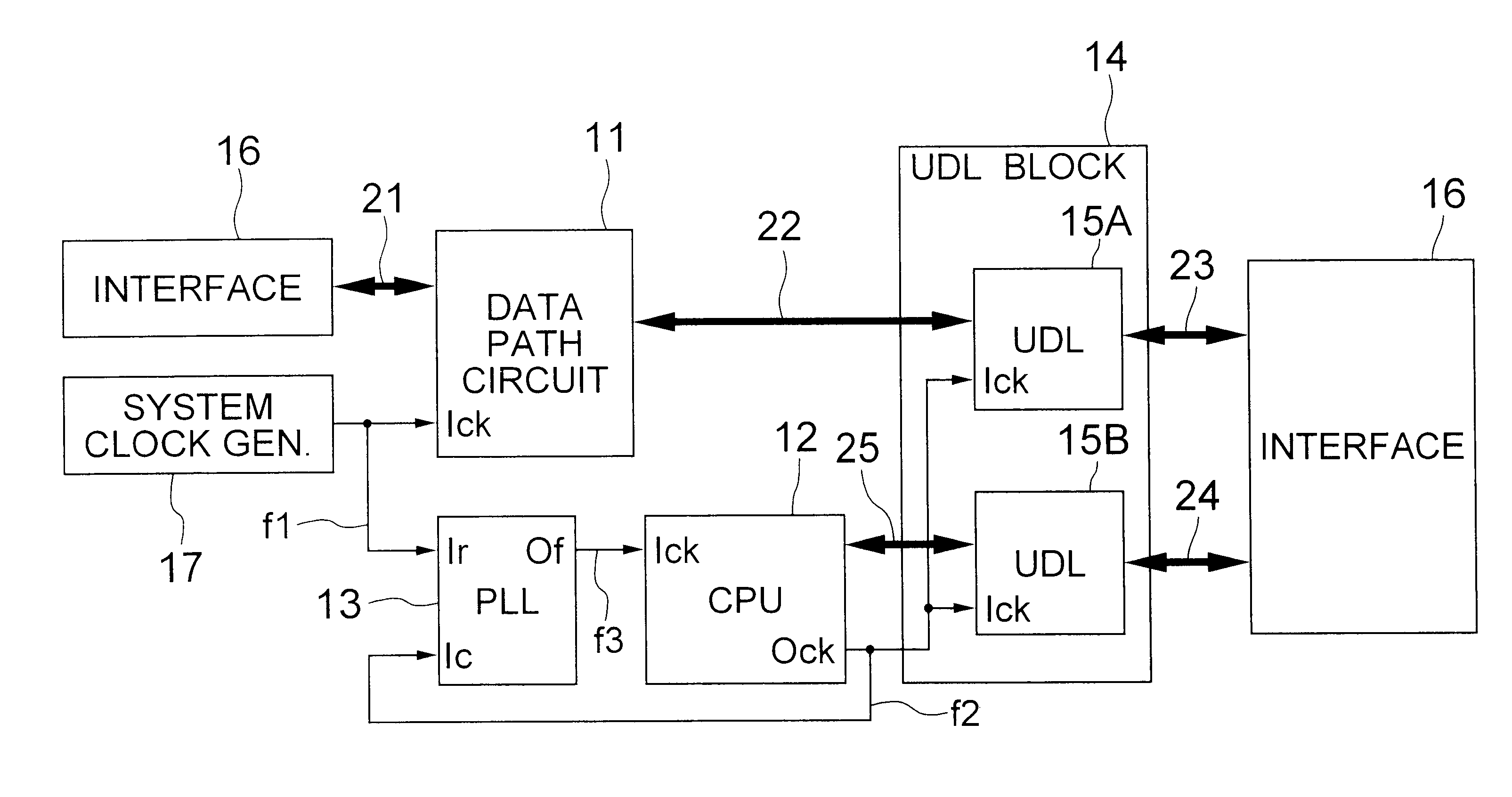
Referring to FIG. 4, a signal processing system according to a first embodiment of the present invention includes a data path circuit 11 as a first processor, a CPU (CPU core) 12 as a second processor, a system clock generator 17 for delivering a system clock signal f1, a PLL circuit 13 for generating a first clock signal f3 based on the system clock signal f1, a set of external interfaces 16, a UDL block 14 as a third processor for receiving / transmitting data, and data buses 21 to 25 for data transmission.

The UDL block 14 includes first UDL circuit 15A and a second UDL circuit 15B, and operates for data transmission between the data path circuit 11 or the CPU 12 and the external interface 16 through the data bus by using the first and second UDL circuits 15A and 15B. The first and second UDL circuits 15A...


PUM


Abstract

A signal processing system includes a PLL circuit for generating a first clock signal based on a system clock signal, a CPU for generating a second clock signal based on the first clock signal and operating with the second clock signal. The PLL circuit receives the second clock signal as a feed-back signal to deliver the first clock signal so that the phases of the second clock signal and the system clock signal coincide with each other. A data path circuit operates with the system clock signal and UDL circuit operates with the second clock signal, whereby the system can be handled as a synchronous circuit operating with the single system clock signal.

Description

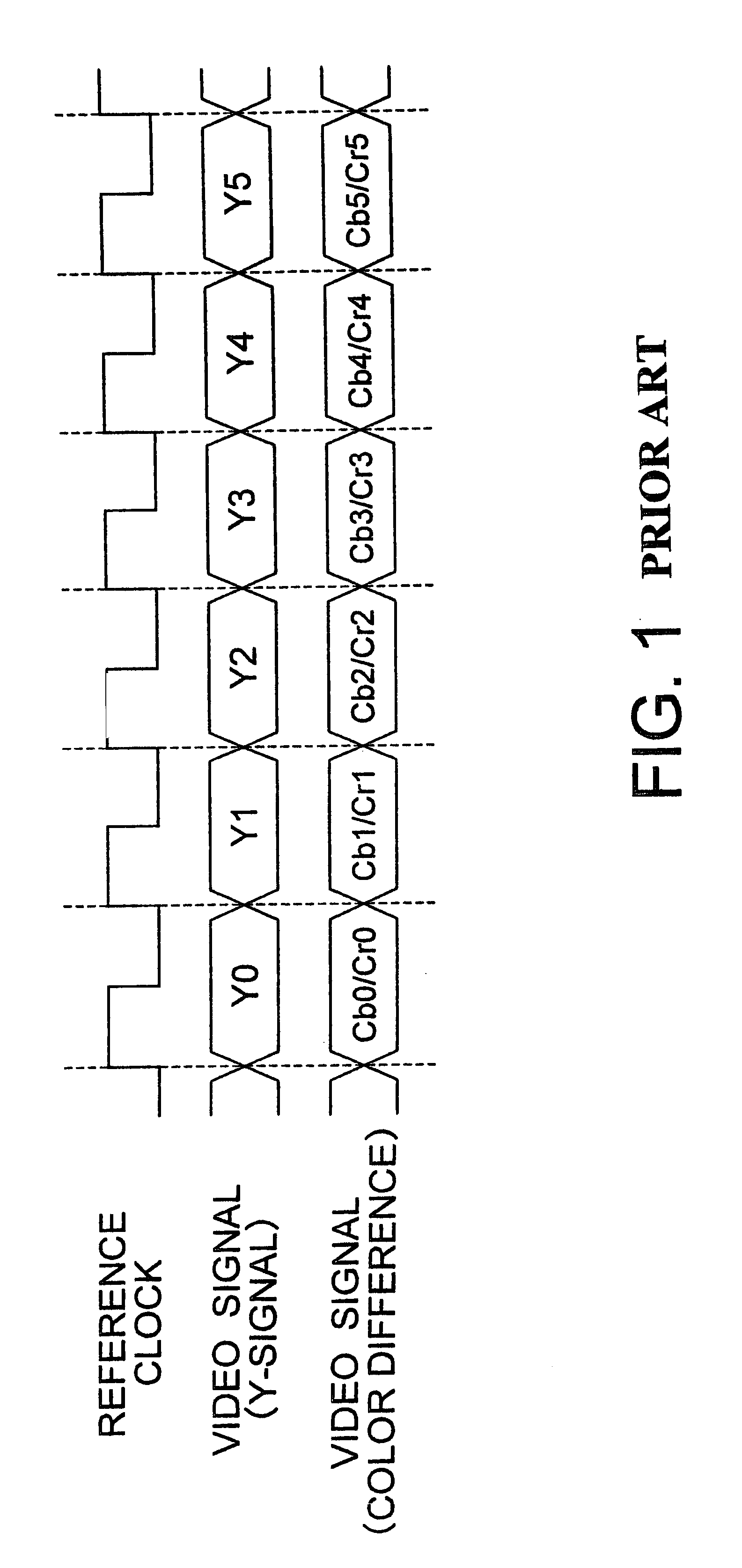
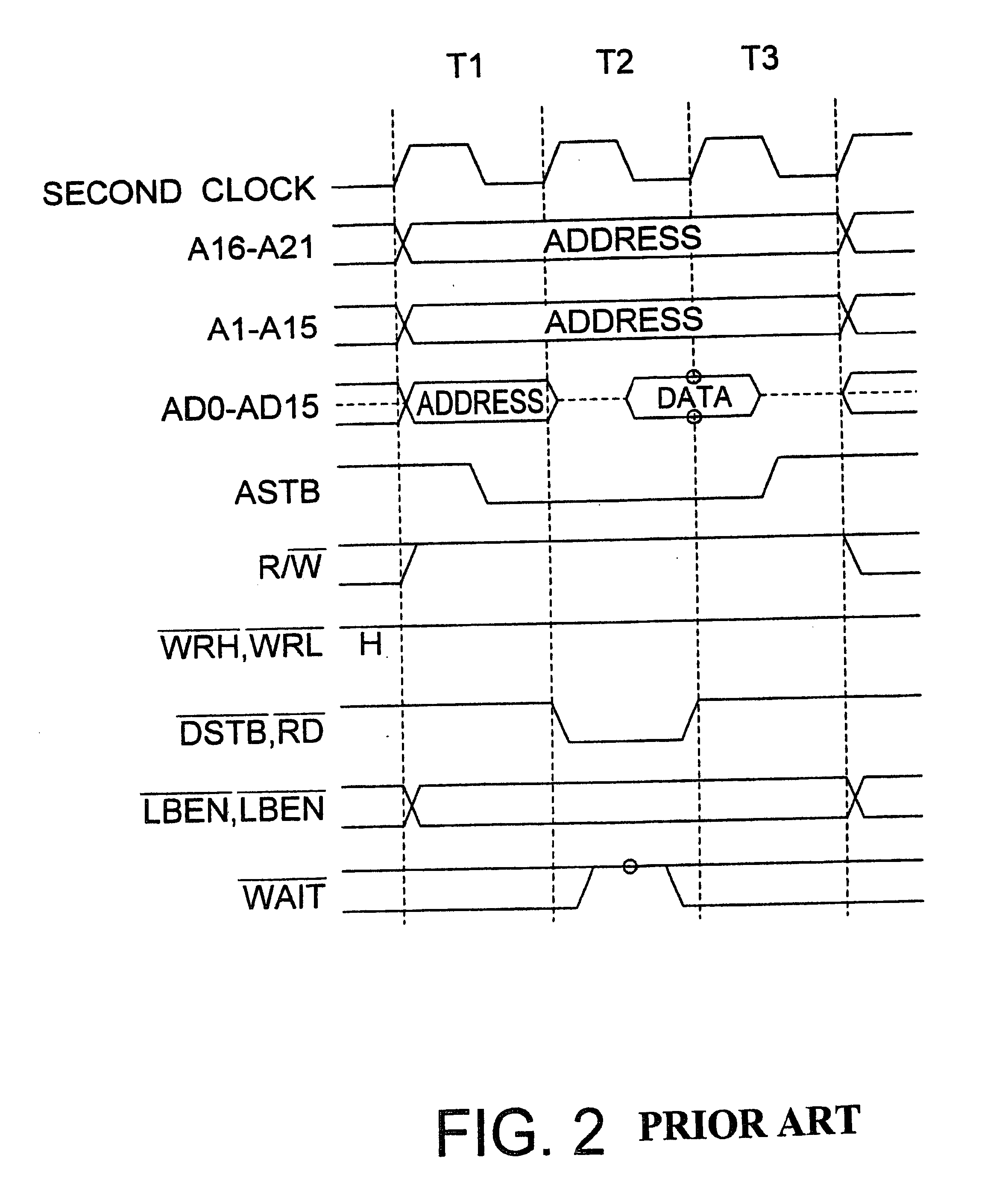
(a) Field of the InventionThe present invention relates to a synchronous signal processing system and, more particularly, to a technique for handling a signal processing system having a plurality of processors operating with different clock signals as a synchronous circuit operating with a single clock signal.(b) Description of a Related ArtIn view of feasibility of larger circuit scale, higher speed operation and circuit design for semiconductor devices, it is desired that a signal processing system including a plurality of processors operating with different clock signals be handled as a synchronous system operating with a single system clock signal.FIG. 1 shows a timing chart of signals in a typical video signal processor, implemented as a video signal sampling circuit. The video signal sampling circuit samples a video signal based on a system clock signal. The sampled video signal is then supplied to a succeeding stage circuit together with the system clock signal for allowing t...

Claims


Application Information

Patent Timeline
Patent Type & Authority Patents(United States)
IPC IPC(8): G06F1/10H03L7/06G06F1/12H04L7/033H04N5/06H04N5/14
CPCG06F1/10H03L7/06
Inventor HIGASHINO, KIMINORI
Owner RENESAS ELECTRONICS CORP
Learn More