
Element Selection Unit and a Method Therein

a technology of element selection and selection unit, applied in the direction of transmission path division, amplitude demodulation, instruments, etc., can solve the problems of increasing the overhead of controlling and configuring data transport, increasing the complexity of signal processing software, and increasing the complexity of signal processing structure, so as to improve the performance of a data processing system

Active Publication Date: 2015-05-07
TELEFON AB LM ERICSSON (PUBL)
View PDF2 Cites 5 Cited by
  • Summary
  • Abstract
  • Description
  • Claims
  • Application Information

AI Technical Summary

Benefits of technology

The present invention provides a way to improve the performance of a data processing system. It achieves this by generating a multiplexer control signal for each multiplexer based on a bit map and relative offset values, and by allowing vector elements to propagate in parallel through multiple layers of multiplexers towards the output vector. This results in high throughput vector element selection, leading to improved system performance. Additionally, the invention reduces the required area and power consumed for the element selection unit as compared to shuffle based systems. It also has a low configuration overhead and a low cost for storing the boolean bit map vector.

Problems solved by technology

The mapping of various types of information channels and signals on these subcarriers can be quite complex and scattered.
The smaller the data blocks are, i.e. the shorter the data bursts are, the larger will the overhead of controlling and configuring the data transport be.
However, it should be noted that the selectivity of the classical DSPs, i.e. the scalar sample granularity, may add complex control structures in the signal processing software.
Further, a device loading and storing one selected scalar element at a time requires quite some time to aggregate all selected data elements.
The selection pattern has the same selection grid as the data element selection of the received symbol streams and would result in a processor load of up to 670 MIPS, which is a significant overhead and has quite some latency.
On-the-fly shuffle pattern and mask pattern calculation give computational overhead on top of the signal processing.
Not all processors support calculation of patterns.
Having all possible patterns hard coded is not possible.
The number of patterns and therefore the required storage memory explodes with increasing vector size.
This makes the pattern table and the lookup process more complex.
This overhead cannot be software pipelined with computational operations, for example of the equalization task.
Adding a shuffle circuit to a vector processor in order to support data element selection is costly in terms of the area and power required.
Further, shuffle circuits are expensive circuits, since the number of two-input multiplexers comprised in the shuffle circuit scales quadratically with the number P of data elements as (P−1)*P. Note that the area of a full shuffle circuit however is dominated by wiring and not so much by standard cells in current Complementary Metal-Oxide-Semiconductor (CMOS) technologies.

Method used


Image

  • Element Selection Unit and a Method Therein
  • Element Selection Unit and a Method Therein
  • Element Selection Unit and a Method Therein

Examples


Embodiment Construction

[0044]Embodiments will be exemplified in the following non-limiting description.

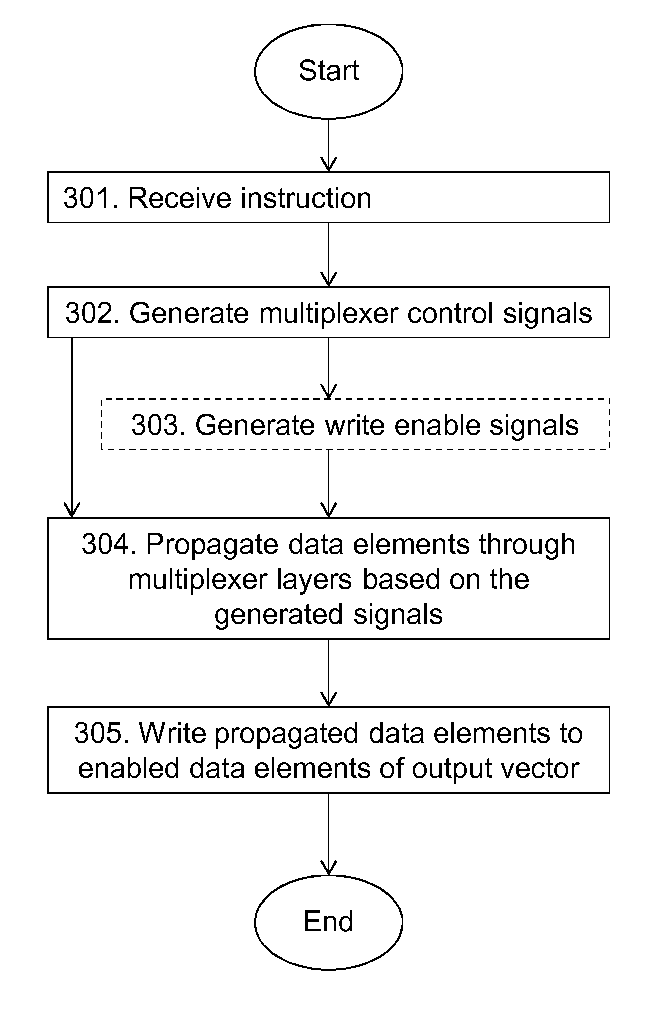
[0045]Embodiments herein relate to a high-throughput low-cost element selection unit. The element selection unit is capable of selecting data elements from an input vector, concatenating the selected data elements, giving the selected set of data elements a common rotation and merging the selected set of data elements with an output vector.

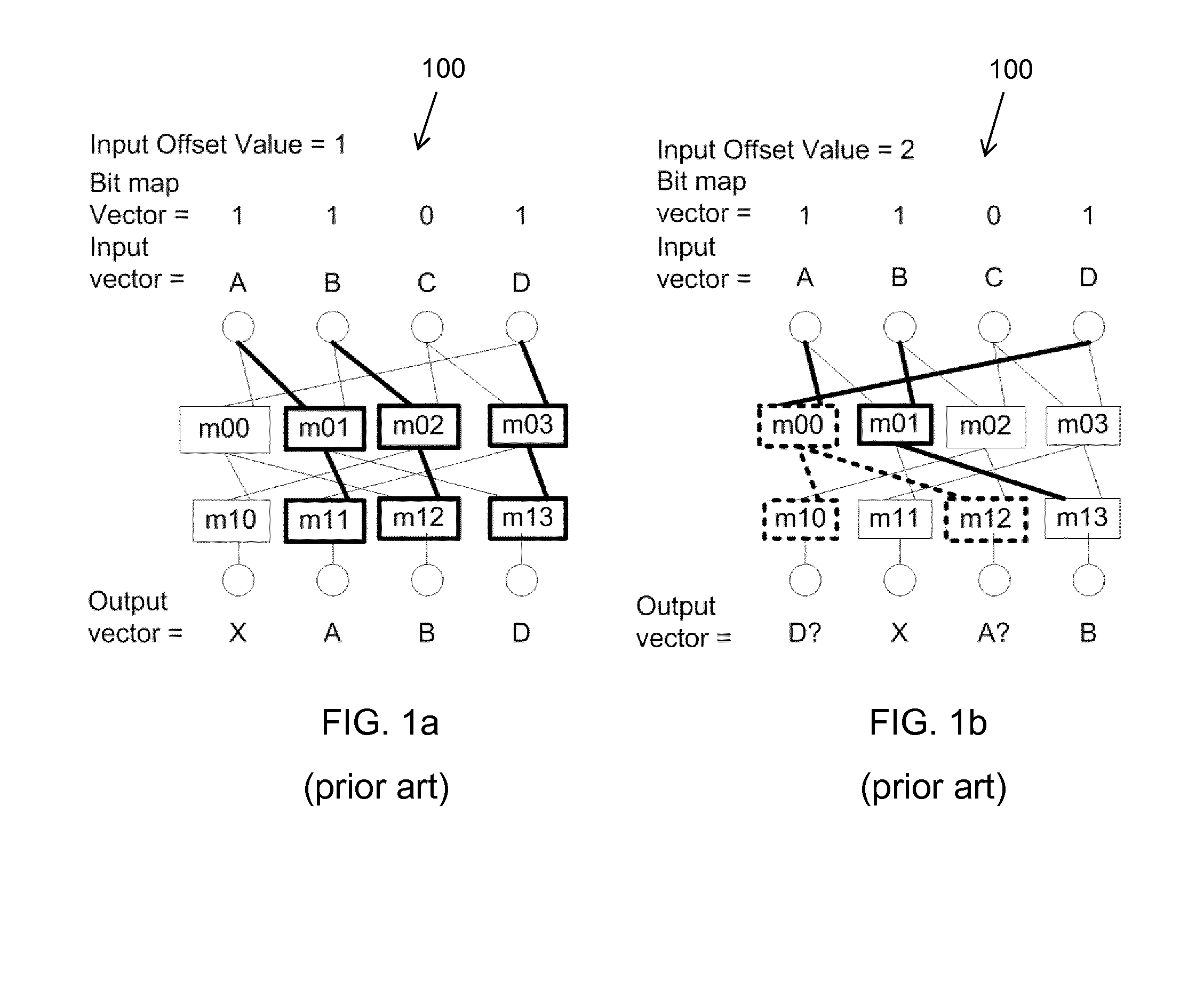
[0046]The selection of data elements from the input vector is based on a selection bit map, i.e. a vector of Boolean values.

[0047]Each data element corresponds to a word, i.e. a fixed size of W′ bits, which is handled as a unit. The word size may for example be equal to 8, 16, or 32 bits.

[0048]The element selection unit comprises (2 log(P)+1) layers with P−1 two-input multiplexers of W bits width, which multiplexers are individually controlled, cf. FIG. 6 which will be described in more detail below. P is the number of data elements in the input vector, and may be equa...


PUM


Abstract

An element selection unit (200) and a method therein for vector element selection. The element selection unit comprises a selector control circuit (404) and a selector data path circuit (406), which data path circuit comprises a plurality of layers of multiplexers. The element selection unit further comprises a receiving circuit (401) configured to receive an instruction to perform a selection of elements from an input vector. The selector control circuit (404) is configured to generate a multiplexer control signal for each multiplexer based on a bit map and on a plurality of relative offset values. The data path circuit is configured to propagate the elements comprised in the input vector through the plurality of layers of multiplexers towards an output vector based on the generated multiplexer control signals. The data path circuit is further configured to write the propagated elements to enabled elements of the output vector.

Description

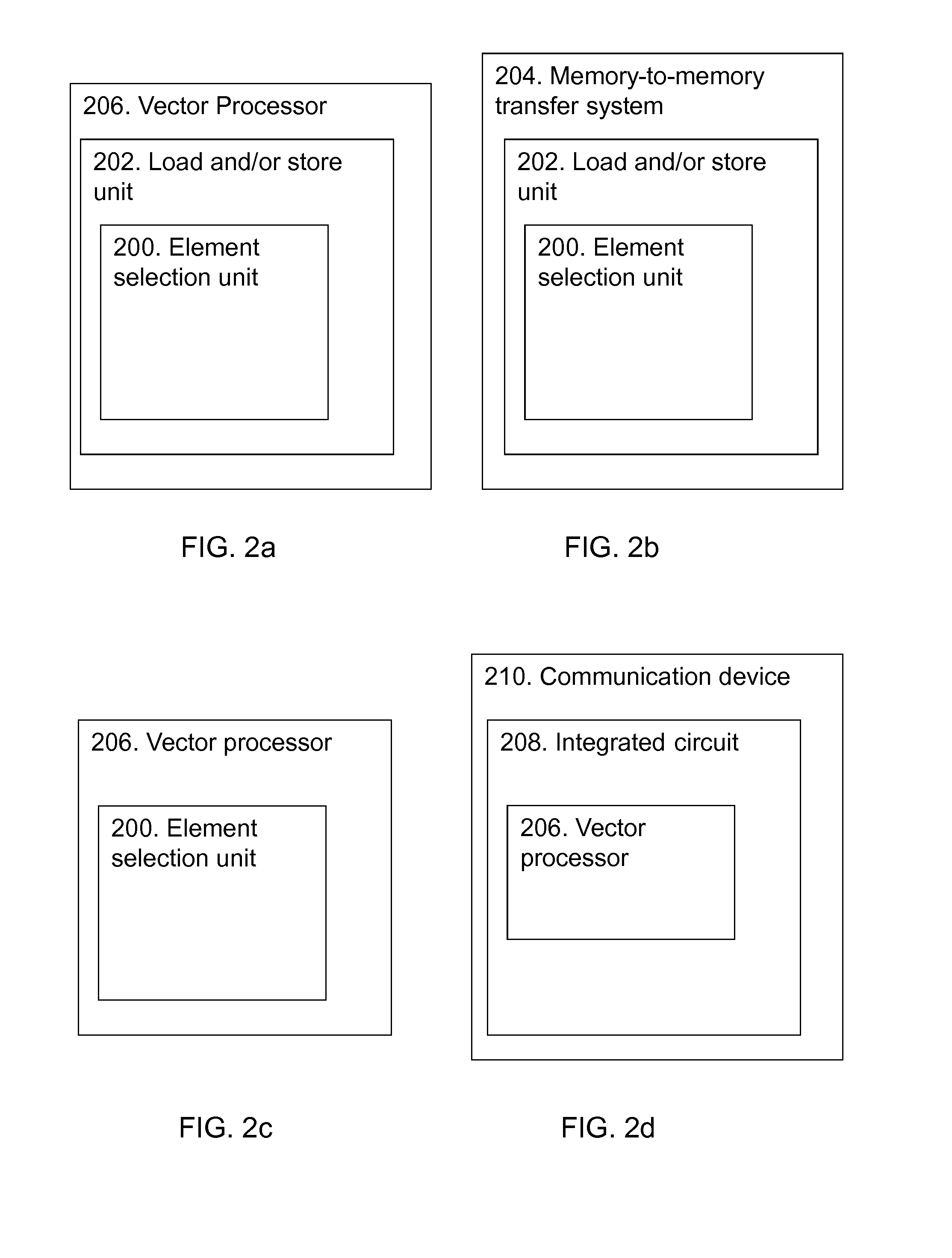
TECHNICAL FIELD[0001]Embodiments herein relates to an element selection unit for vector element selection, and to a method therein. Further embodiments relate to a load store unit comprising the element selection unit, a memory-to-memory transfer system comprising the element selection unit, a vector processor comprising the element selection unit, and to an integrated circuit comprising the vector processor.BACKGROUND[0002]For some digital signal processing algorithms, input data has to be aggregated or organized before computation can start. For example, when selecting a scattered set of data elements from a linear input vector, the selected data elements have to be aggregated into a new linear output vector of subsequent data elements before computation can start. Such type of data aggregation or organization is for example required in the equalization processing of data subcarriers in 3GPP Long Term Evolution (LTE) communication systems. LTE is a wireless communication standard ...

Claims


Application Information

Patent Timeline
Patent Type & Authority Applications(United States)
IPC IPC(8): H04L27/26H04L5/00
CPCH04L5/0001H04L27/2649G06F15/8076G06F9/30032G06F9/30036
Inventor VAN KAMPEN, DAVID
Owner TELEFON AB LM ERICSSON (PUBL)
Learn More