Transmission system with high frequency stability

a transmission system and high frequency stability technology, applied in transmission, electrical equipment, selection arrangements, etc., can solve the problems of interference between the zones, high cost,

Inactive Publication Date: 2008-07-08
THOMSON MULTIMEDIA SA +1
View PDF11 Cites 7 Cited by
  • Summary
  • Abstract
  • Description
  • Claims
  • Application Information

AI Technical Summary

Benefits of technology

[0012]The invention proposes a transmission system in which the position of the synchronization subcarrier can be placed at various locations of the band allotted to an operator. The external unit of the reception device comprises additional transposition means which make it possible to reduce the synchronization subcarrier down to a predefined frequency span independently of its position in the transmission frequency band.
[0016]To minimize the frequency error of a return link, the unit comprising uplink means for transposing and amplifying a return frequency band which includes at least one uplink channel from a low frequency band to a return link transmission bard, and the said uplink means carry out a first frequency transposition with the local oscillator.

Problems solved by technology

But the external unit 1 is subjected to temperature and climate constraints which make it difficult and hence very expensive to achieve such stability.
The use of a fixed frequency for the entire distribution network would cause interference between the zones using one and the same frequency.

Method used


Image

  • Transmission system with high frequency stability
  • Transmission system with high frequency stability
  • Transmission system with high frequency stability

Examples


Embodiment Construction

[0025]In the present document, the labels in the figures using one and the same set of initials are used for identical or similar elements.

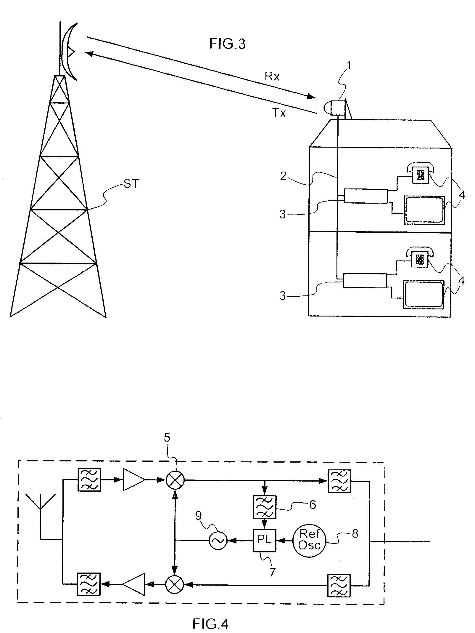
[0026]FIG. 5 represents a first embodiment of an external unit according to the invention. An antenna 100 serves to receive the signals originating from the base station and to transmit signals to this same base station. The transmission band consists of two disjoint frequency planes, one for the down signals and the other for the up signals. By way of example, the down signals lie between 40.5 and 41 GHz and the up signals lie between 41.5 and 41.6 GHz.

[0027]For the downlink, a bandpass filter 101 linked to the antenna selects the useful band for example the 40.5 to 41 GHz band. An amplifier 102 amplifies the signals leaving the filter 101. A mixer 103 mixes the signals originating from the amplifier 102 with a signal at a transposition frequency originating from an oscillator 104. The oscillator 104 is for example a Dielectric Resonator Oscilla...


PUM


Abstract

The invention proposes a transmission system using a reference subcarrier to synchronize a local oscillator 104. The reference subcarrier can be placed at various locations of the band allotted to an operator. The external unit 1 of the reception device comprises frequency-wise selection means 107 which make it possible to select the synchronization subcarrier.

Description

FIELD OF THE INVENTION[0001]The invention pertains to a transmission system with high frequency stability. More particularly, the invention concerns an external unit placed on a subscriber side.BACKGROUND OF THE INVENTION[0002]Radio transmission systems of point-multipoint type are known to the person skilled in the art by the initials MMDS (standing for Microwave Multipoint Distribution System), LMDS (standing for Local Multipoint Distribution System) and MVDS (standing for Multipoint Video Distribution System). These systems used for the broadcasting of programmes permit a return link for the subscriber terminals which allows the subscriber to interact with the programme received.[0003]In Europe, provision has been made to implement a system of LMDS type which has 24 broadcasting channels (also referred to as downlinks) having a bandwidth of 33 MHz, and 25 return channels (or uplinks) having a bandwidth of 2 MHz, these channels being situated between 40.5 and 42.5 GHz (for further...

Claims


Application Information

Patent Timeline
Patent Type & Authority Patents(United States)
IPC IPC(8): H04B1/02H04B1/40H04B1/10H04B1/28H04Q7/28
CPCH04B1/28H04B1/1027
Inventor MOCQUARD, OLIVIERLE NAOUR, JEAN-YVES
Owner THOMSON MULTIMEDIA SA
Why Eureka
Try Eureka