Ultra low-power high frequency crystal oscillator for real time clock applications

a crystal oscillator and high frequency technology, applied in the field of oscillator circuits, can solve the problems of increasing cost, increasing frequency, and consuming a significant amount of circuit area, and achieve the effects of reducing capacitance values, minimizing power consumption, and minimizing frequency errors of clock signals

Active Publication Date: 2015-08-18
QUALCOMM INC
View PDF13 Cites 0 Cited by
  • Summary
  • Abstract
  • Description
  • Claims
  • Application Information

AI Technical Summary

Benefits of technology

[0006]When the oscillator circuit is to operate in the normal mode, the mode signal may be driven to a first state that sets the capacitance values of the first and second variable capacitors to nominal values that cause the oscillator circuit to generate a high-accuracy reference clock signal in a manner that minimizes a frequency error of the clock signal. The first state of the mode signal may also cause the switching circuit to couple the first amplifier circuit across the crystal and to isolate the second amplifier circuit from the crystal.
[0007]When the oscillator circuit is to operate in the low-power mode, the mode signal may be driven to a second state that sets the capacitance values of the first and second variable capacitors to relatively low (e.g., to minimum) values that cause the oscillator circuit to generate a low-power RTC signal in a manner that minimizes power consumption (e.g., as compared to the normal mode). Although reducing the capacitance values of the first and second variable capacitors may increase the frequency error of the clock signal generated by the oscillator circuit, the frequency error may be predicted and accounted for (e.g., using a compensation circuit). The second state of the mode signal may also cause the switching circuit to couple the second amplifier circuit across the crystal and to isolate the first amplifier circuit from the crystal.
[0008]For some embodiments, the oscillator circuit may also include one or more automatic gain control circuits that may monitor an amplitude of the clock signal and, in response thereto, may adjust a bias current provided to either the first or second amplifier circuit, for example, to minimize power consumption. A common automatic gain control circuit, or alternatively two different automatic gain control circuits optimized for the two different modes of operation, may be used.

Problems solved by technology

However, the inclusion of multiple crystal oscillators in a communication device may consume a significant amount of circuit area and increase cost.
Although reducing the capacitance values of the first and second variable capacitors may increase the frequency error of the clock signal generated by the oscillator circuit, the frequency error may be predicted and accounted for (e.g., using a compensation circuit).

Method used


Image

  • Ultra low-power high frequency crystal oscillator for real time clock applications
  • Ultra low-power high frequency crystal oscillator for real time clock applications
  • Ultra low-power high frequency crystal oscillator for real time clock applications

Examples


Embodiment Construction

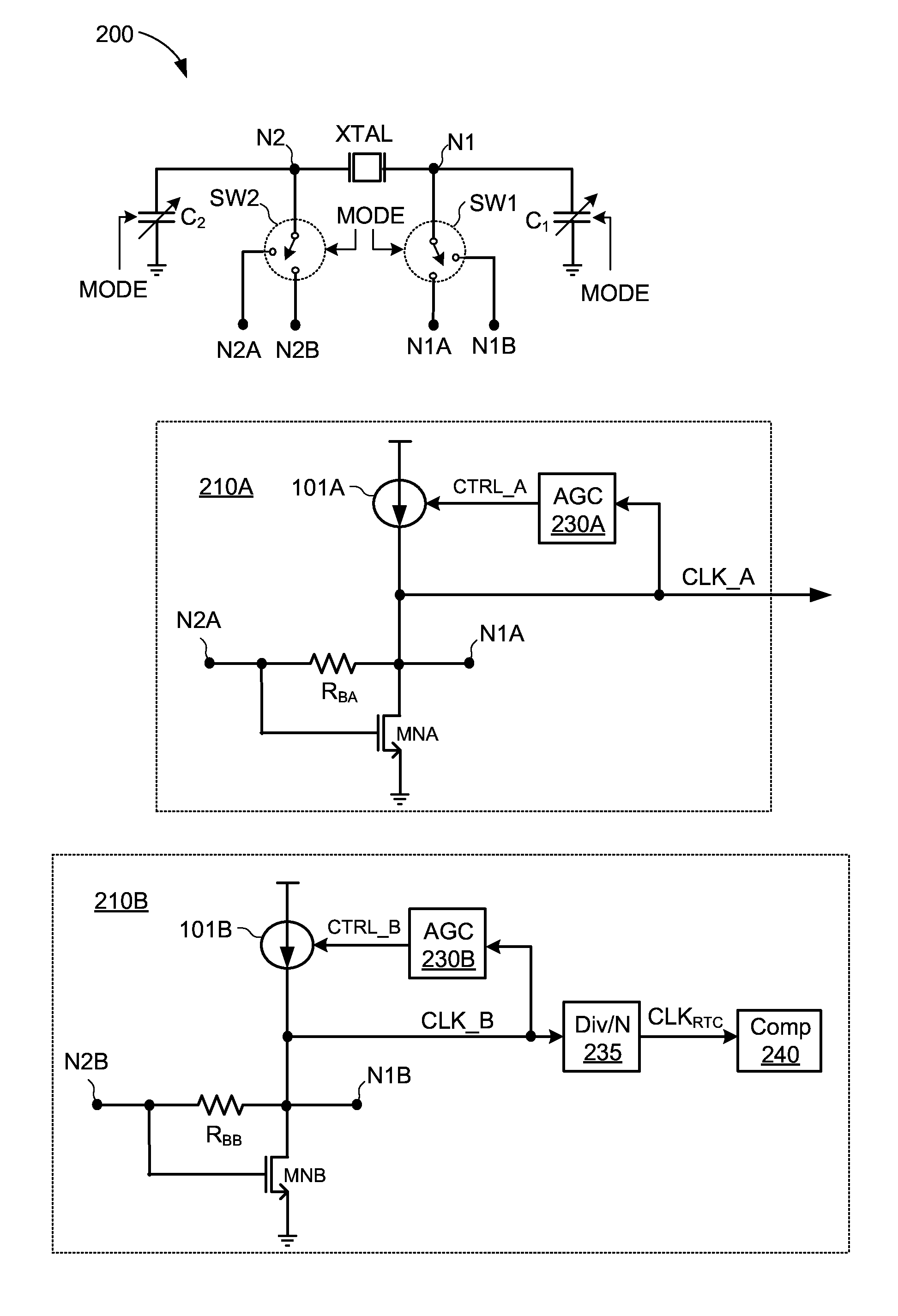
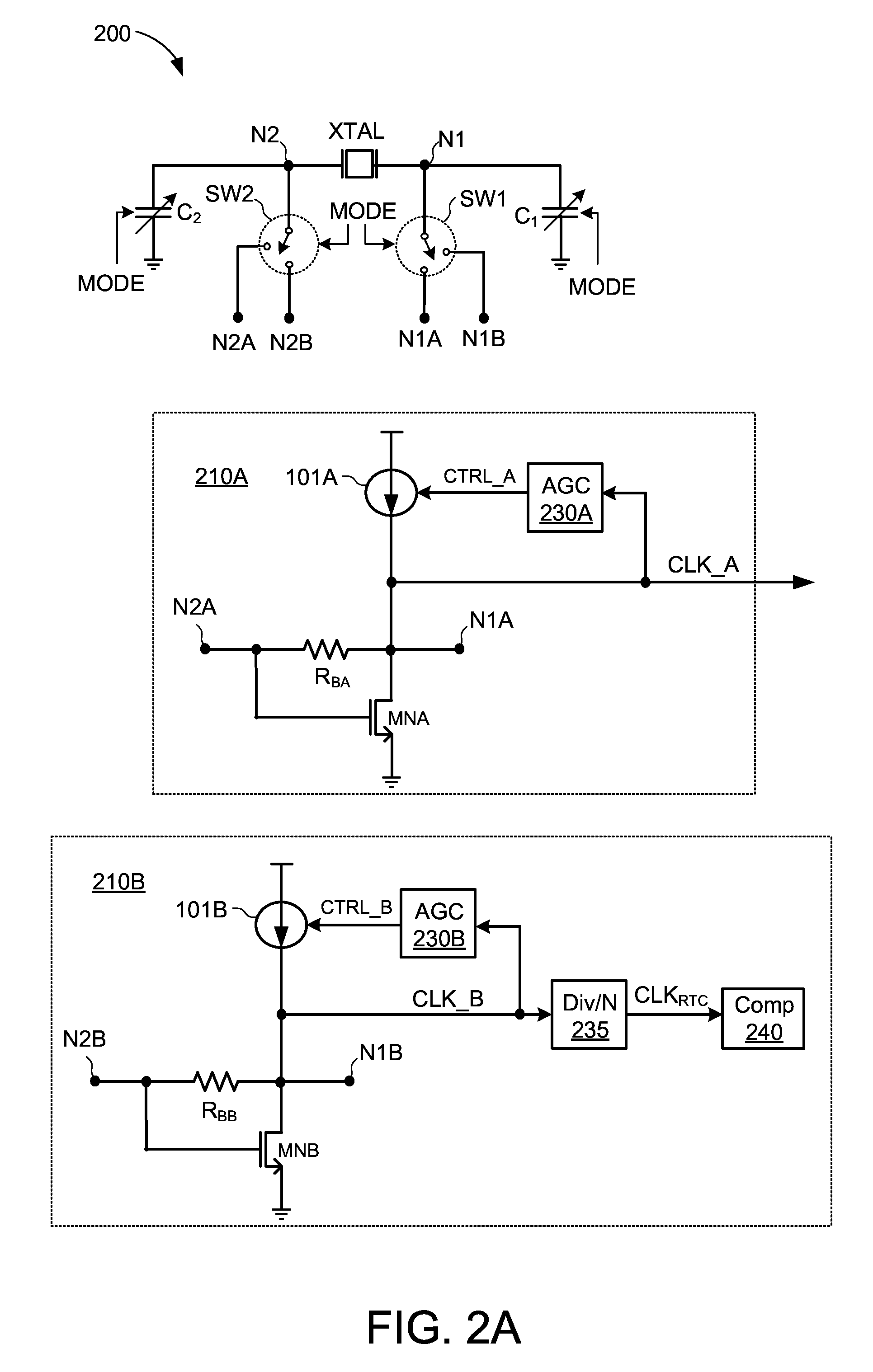
[0017]A method and apparatus for generating clock signals using oscillator circuits having a normal mode of operation and a low-power mode of operation are disclosed. In the following description, numerous specific details are set forth to provide a thorough understanding of the present disclosure. Also, in the following description and for purposes of explanation, specific nomenclature is set forth to provide a thorough understanding of the present embodiments. However, it will be apparent to one skilled in the art that these specific details may not be required to practice the present embodiments. In other instances, well-known circuits and devices are shown in block diagram form to avoid obscuring the present disclosure. The term “coupled” as used herein means connected directly to or connected through one or more intervening components or circuits. Any of the signals provided over various buses described herein may be time-multiplexed with other signals and provided over one or ...


PUM


Abstract

An oscillator circuit may selectively switch between a normal mode and a low-power mode in response to a mode signal. During the normal mode, the oscillator circuit may employ a first amplifier configuration and a first capacitive loading to generate a high-accuracy clock signal having a relatively low frequency error. During the low power mode, the oscillator circuit may employ a second amplifier configuration and a second capacitive loading to generate a low-power clock signal using minimal power consumption. A compensation circuit may be used to offset a relatively high frequency error during the low-power mode.

Description

TECHNICAL FIELD[0001]The present embodiments relate generally to oscillator circuits, and specifically to oscillator circuits that may operate in a normal mode or in a low-power mode.BACKGROUND OF RELATED ART[0002]Crystal oscillators generate timing signals for many components of communication devices (e.g., smartphones). For example, crystal oscillators may be used to generate a highly accurate reference clock signal that, in turn, may be used by frequency synthesizers to generate RF carrier signals (e.g., to facilitate wireless data transmissions). Crystal oscillators may also be used to generate low-power real-time clock (RTC) signals that, in turn, may be used for timekeeping functions during low-power modes (e.g., to allow a mobile station to wake-up from a sleep state at certain intervals to listen for beacon transmissions from an associated access point). As a result, communication devices typically include one crystal oscillator to generate the high frequency reference clock...

Claims


Application Information

Patent Timeline
Patent Type & Authority Patents(United States)
IPC IPC(8): H03B5/36
CPCH03B5/362H03B5/364H03B2200/005H03B2200/0046H03B2200/0052H03B2200/0082H03B2201/0266
Inventor TERROVITIS, EMMANOUIL
Owner QUALCOMM INC
Why Eureka
Try Eureka