Trigger forward displacement system and method

a forward displacement and forward displacement technology, applied in the direction of firing/trigger mechanisms, weapons, weapon components, etc., to achieve the effects of low manufacturing cost, convenient and efficient manufacturing and marketing, and durable and reliable construction

Active Publication Date: 2008-07-15
ABC IP LLC
View PDF8 Cites 56 Cited by
  • Summary
  • Abstract
  • Description
  • Claims
  • Application Information

AI Technical Summary

Benefits of technology

[0025]It is another object of the present invention to provide a new and improved trigger forward displacement system and method which may be easily and efficiently manufactured and marketed.
[0026]It is further an object of the present invention to provide a new and improved trigger forward displacement system and method which is of durable and reliable construction.
[0027]An even further object of the present invention is to provide a new and improved trigger forward displacement system and method which is susceptible of a low cost of manufacture with regard to both materials and labor, and which accordingly is then susceptible of low prices of sale to the consuming public, thereby making such trigger forward displacement system and method economically available to the buying public.
[0028]Even still another object of the present invention is to provide a trigger forward displacement system and method for increasing the cyclic rate of actuating the trigger and discharging a semi-automatic firearm.

Problems solved by technology

While these devices fulfill their respective, particular objectives and requirements, the aforementioned patents do not describe a trigger forward displacement system and method that allows increasing the cyclic rate of actuating the trigger and discharging a semi-automatic firearm.

Method used


Image

  • Trigger forward displacement system and method
  • Trigger forward displacement system and method
  • Trigger forward displacement system and method

Examples


Embodiment Construction

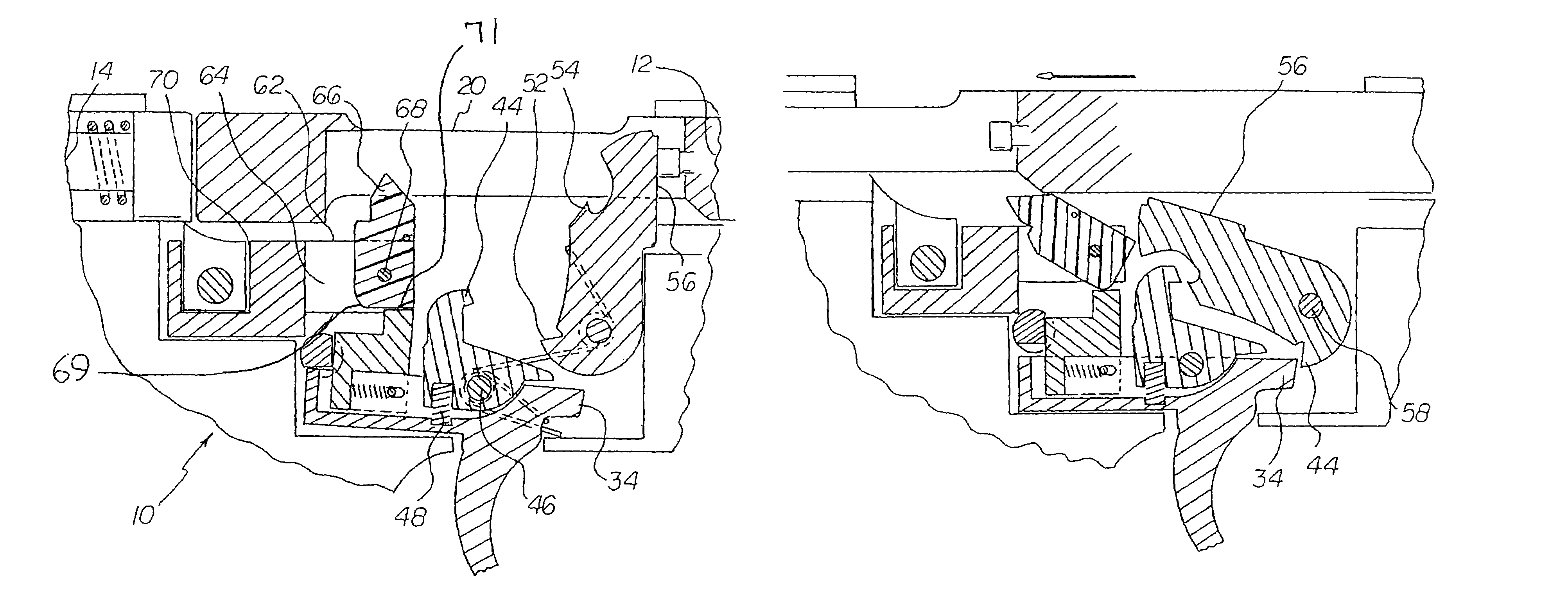
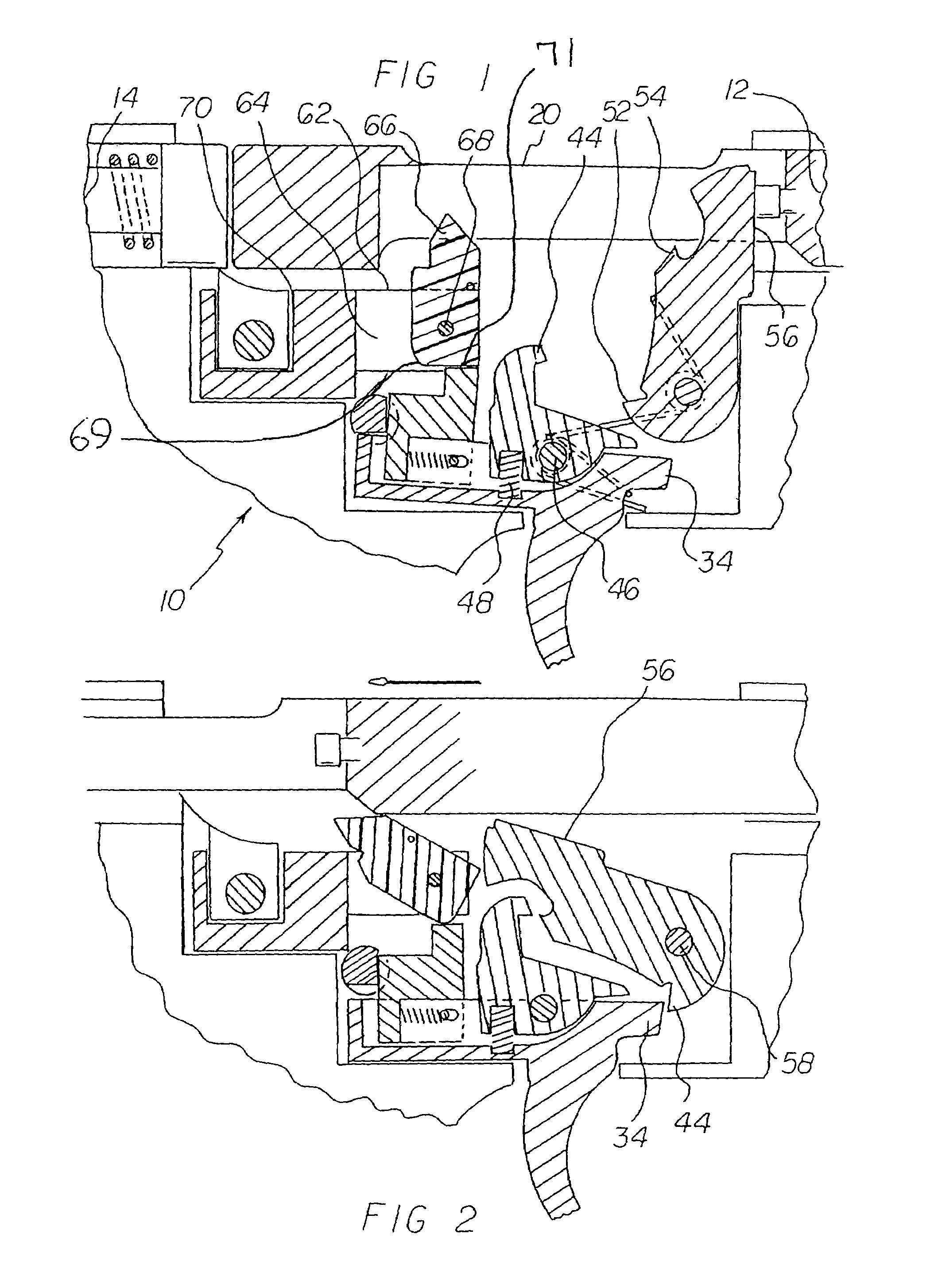
[0038]With reference now to the drawings, and in particular to FIG. 1 thereof, the preferred embodiment of the new and improved trigger forward displacement system and method embodying the principles and concepts of the present invention and generally designated by the reference numeral 10 will be described.

[0039]The present invention, the trigger forward displacement system and method 10 is comprised of a plurality of components. Such components in their broadest context include a semi-automatic firearm, a trigger, a disconnector, a trigger mounting pin, a trigger disconnector spring, a hammer, a hammer mounting pin, a hammer spring, a cam body assembly, a safety selector, and a trigger extender. Such components are individually configured and correlated with respect to each other so as to attain the desired objective.

[0040]First provided is a semi-automatic firearm. The semi-automatic firearm has a forward end 12 and a rearward end 14. The semi-automatic firearm is comprised of a ...


PUM


Abstract

A semi-automatic firearm has forward and rearward ends. A receiver has a safety selector aperture, a barrel, a reciprocating loading mechanism and a magazine. A trigger finger and inner portions. The inner portion has a seat with a groove. A disconnector has a hammer hook coupled to the trigger. A trigger mounting pin couples the trigger to the firearm. A trigger disconnector spring couples the trigger and the disconnector. A hammer having an upper striking portion with a disconnector hook receptacle. A hammer mounting pin couples the hammer to the firearm. A hammer spring is coupled to the hammer and hammer mounting pin. A cam body subassembly comprises a cam body housing, a cam and a cam mounting pin. The cam body subassembly is coupled to the firearm. A safety selector is coupled to the firearm. A trigger extender is mated with the upward trigger groove.

Description

BACKGROUND OF THE INVENTION[0001]1. Field of the Invention[0002]The present invention relates to a trigger forward displacement system and method and more particularly pertains to increasing the cyclic rate of actuating the trigger and discharging a semi-automatic firearm.[0003]2. Description of the Prior Art[0004]The use of accelerating assemblies for semi-automatic firearms is known in the prior art. More specifically, accelerating assemblies for semi-automatic firearms previously devised and utilized for the purpose of accelerating the cyclic firing rate of semi-automatic firearms are known to consist basically of familiar, expected, and obvious structural configurations, notwithstanding the myriad of designs encompassed by the crowded prior art which has been developed for the fulfillment of countless objectives and requirements.[0005]By way of example, U.S. Pat. No. 6,101,918 issued Aug. 15, 2000 to Akins discloses a method and apparatus for accelerating the cyclic firing rate ...

Claims


Application Information

Patent Timeline
Patent Type & Authority Patents(United States)
IPC IPC(8): F41A19/02
CPCF41A19/12F41A19/10
Inventor BLAKLEY, BRIAN A.
Owner ABC IP LLC
Why Eureka
Try Eureka