MEMS resettable timer

a mechanical timer and timer technology, applied in the direction of fuse connectors, weapons, fuse connectors, etc., can solve the problems of not only a power supply but a signal processor, and the volume of the required components is significant, and existing mechanical timers can also provide the necessary delay

Inactive Publication Date: 2008-07-15
NAVY UNITED STATES OF AMERICA THE AS REPRESENTED BY THE THE
View PDF21 Cites 23 Cited by
  • Summary
  • Abstract
  • Description
  • Claims
  • Application Information

AI Technical Summary

Benefits of technology

[0006]An aspect of an exemplary embodiment of the present invention includes a resettable timer, which includes a primary inertial element and a plurality of secondary inertial elements at an initial position. A locking arrangement prevents movement of all but a first of the inertial elements. Movement of the first inertial element, due to an acceleration of the timer, is operable to commence an unlocking of the locking arrangement to allow sequential movement of the other inertial elements. A reset arrangement is also provi

Problems solved by technology

One problem with the accelerometer, however, is that it requires not only a power supply but a signal processor as well.
Such arrangement needs a significant volume to package the necessary components, which is impractical for various situations, including use in a munition

Method used


Image

  • MEMS resettable timer
  • MEMS resettable timer
  • MEMS resettable timer

Examples


Embodiment Construction

[0011]In the drawings, which are not necessarily to scale, like or corresponding parts are denoted by like or corresponding reference numerals.

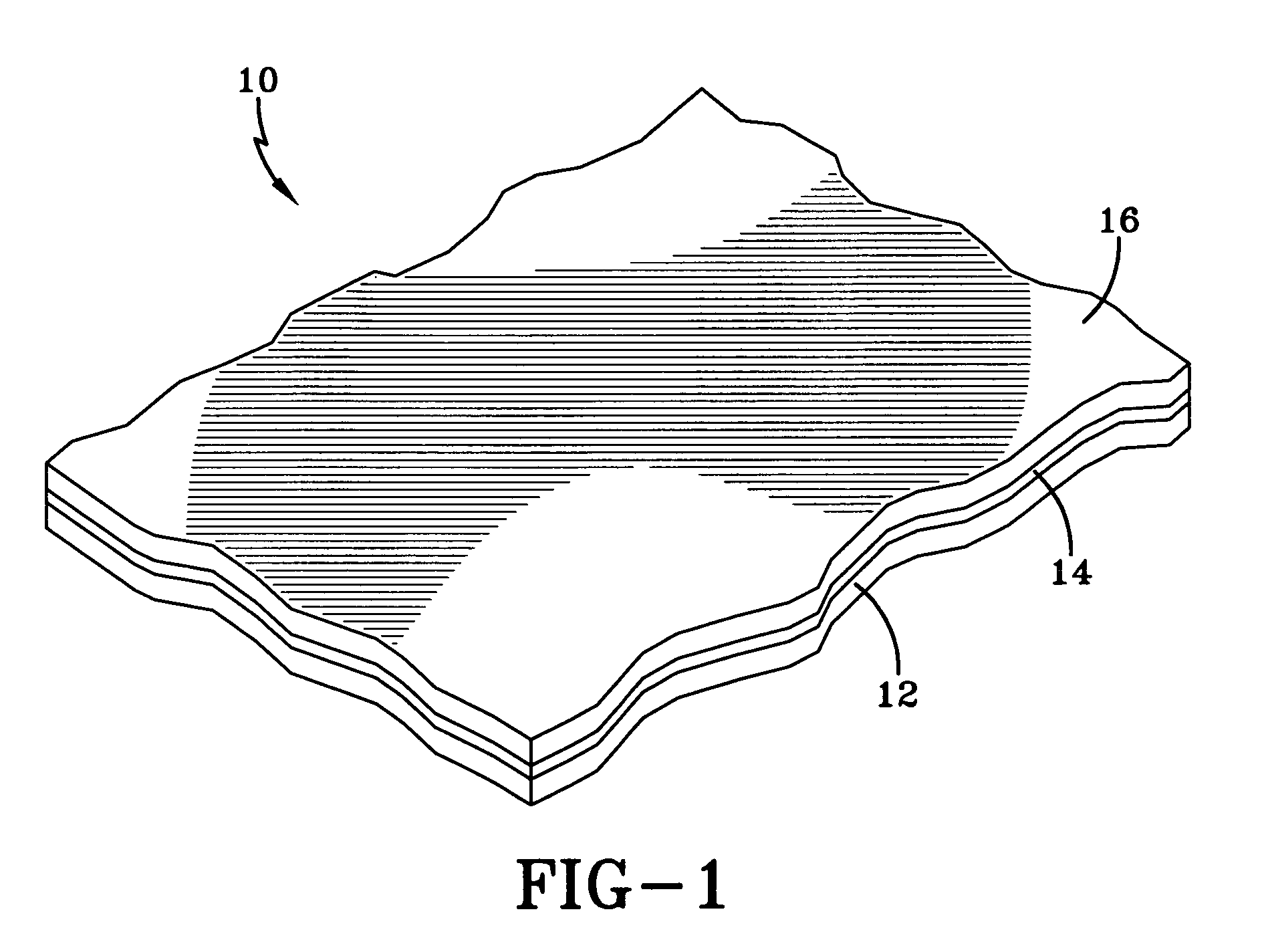
[0012]FIG. 1 illustrates a portion of an SOI wafer 10 from which the timer of the present invention may be fabricated. The structure of FIG. 1 includes a silicon substrate 12 (also known as a handle layer) covered by an insulating layer 14, such as silicon dioxide, over which is deposited another silicon layer 16 (also known as the device layer), which is the layer from which the timer will be produced.

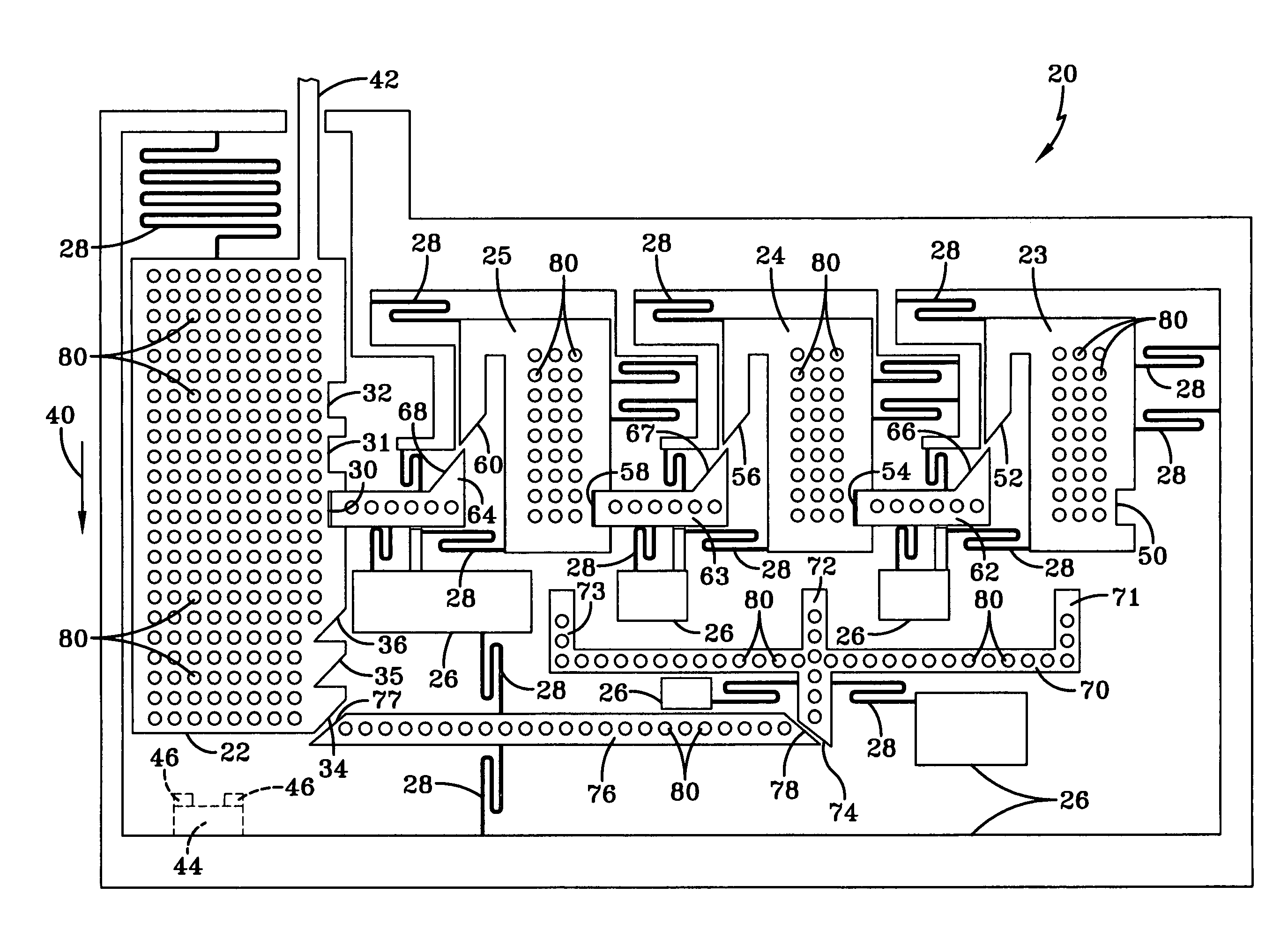
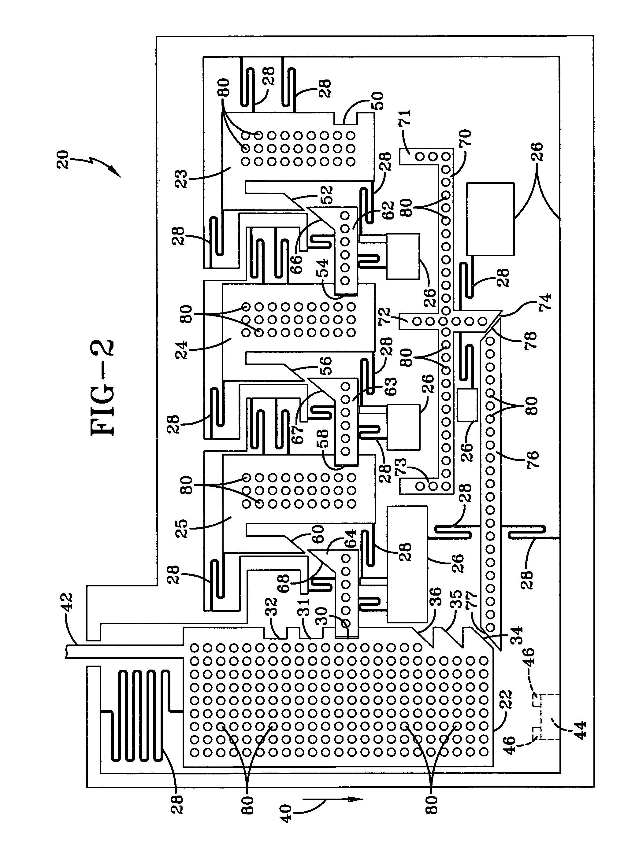
[0013]FIG. 2 is a view of one embodiment of a timer 20 formed from the wafer 10 of FIG. 1. The timer is formed by a DRIE (deep reactive ion etching) process, which removes unwanted portions of layer 16. The DRIE process is a well developed micromachining process used extensively with silicon based MEMS devices. For this reason silicon is generally a material used for the timer of the present invention, although other materials are possible. Tim...


PUM


Abstract

A MEMS resettable timer including a primary inertial element and at least one secondary inertial element, which includes a camming surface. When the secondary inertial element moves, its camming surface engages the camming surface of a locking element to remove it from the notch of a subsequent inertial element. When the primary inertial element is released for movement it activates a resetting arrangement to place the secondary inertial element back to the initial position and prevent further movement of the primary inertial element. The cycle is repeatable to commence some predetermined action.

Description

STATEMENT OF GOVERNMENT INTEREST[0001]The invention described herein may be manufactured and used by or for the Government of the United States of America for government purposes without the payment of any royalties therefore.BACKGROUND OF THE INVENTION[0002]Various scenarios exist where it is desirable to delay the initiation of an event until some time after an initial shock or acceleration. By way of example, in order to prevent premature detonation, many munition rounds, such as artillery shells, go through a multi-stage arming sequence after being fired. It is required that the sequence commence only after the shell has been fired, and for this purpose a delay after firing is imposed in the procedure.[0003]One way of providing the necessary delay is by the use of an accelerometer. One problem with the accelerometer, however, is that it requires not only a power supply but a signal processor as well. Such arrangement needs a significant volume to package the necessary components...

Claims


Application Information

Patent Timeline
IPC IPC(8): F42C15/24
CPCF42C15/24
Inventor JEAN, DANIEL L.
Owner NAVY UNITED STATES OF AMERICA THE AS REPRESENTED BY THE THE
Why Eureka
Try Eureka