
Pipe lining method

a pipe lining and flange technology, applied in the direction of surface layering apparatus, transportation and packaging, manufacturing tools, etc., can solve the problems of water leakage into the pipe, damage to the lining, and adverse effects on the bond between the main pipe lining material and the flange of the lateral pipe lining material

Inactive Publication Date: 2008-07-15
SHONAN GOSEI JUSHI SEISAKUSHO KK
View PDF14 Cites 18 Cited by
  • Summary
  • Abstract
  • Description
  • Claims
  • Application Information

AI Technical Summary

Benefits of technology

"The present invention provides a method for lining pipes, where a lateral pipe is lined before the main pipe. The method involves using a special material to line the lateral pipe and then inserting a start liner into the main pipe. A curable resin is then applied to the start liner and the main pipe, and the resin is cured to line the main pipe. The method also includes melting the start liner to integrate the main pipe lining material and the flange of the lateral pipe lining material. The technical effect of this invention is to provide a more efficient and effective method for lining pipes, allowing for better protection and integrity of the pipe system."

Problems solved by technology

Therefore, a problem will arise in that, when the main pipe is lined after a start liner has been applied, the bond between the main pipe lining material and the flange of the lateral pipe lining material will be adversely affected by the start liner, the main pipe lining material and the lateral pipe lining material will not be properly joined, water will leak into the pipe from the inadequately connected portion, and defects will occur in the lining.

Method used


Image

  • Pipe lining method
  • Pipe lining method
  • Pipe lining method

Examples


Embodiment Construction

[0023]The present invention will now be described in detail with reference to the embodiments shown in the drawings.

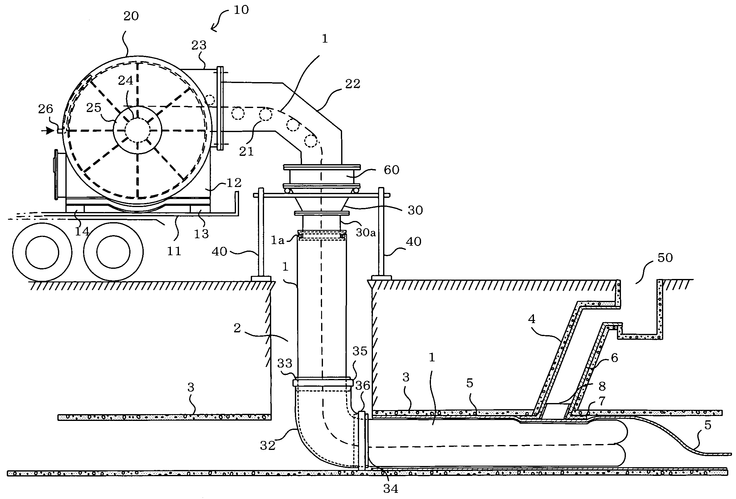
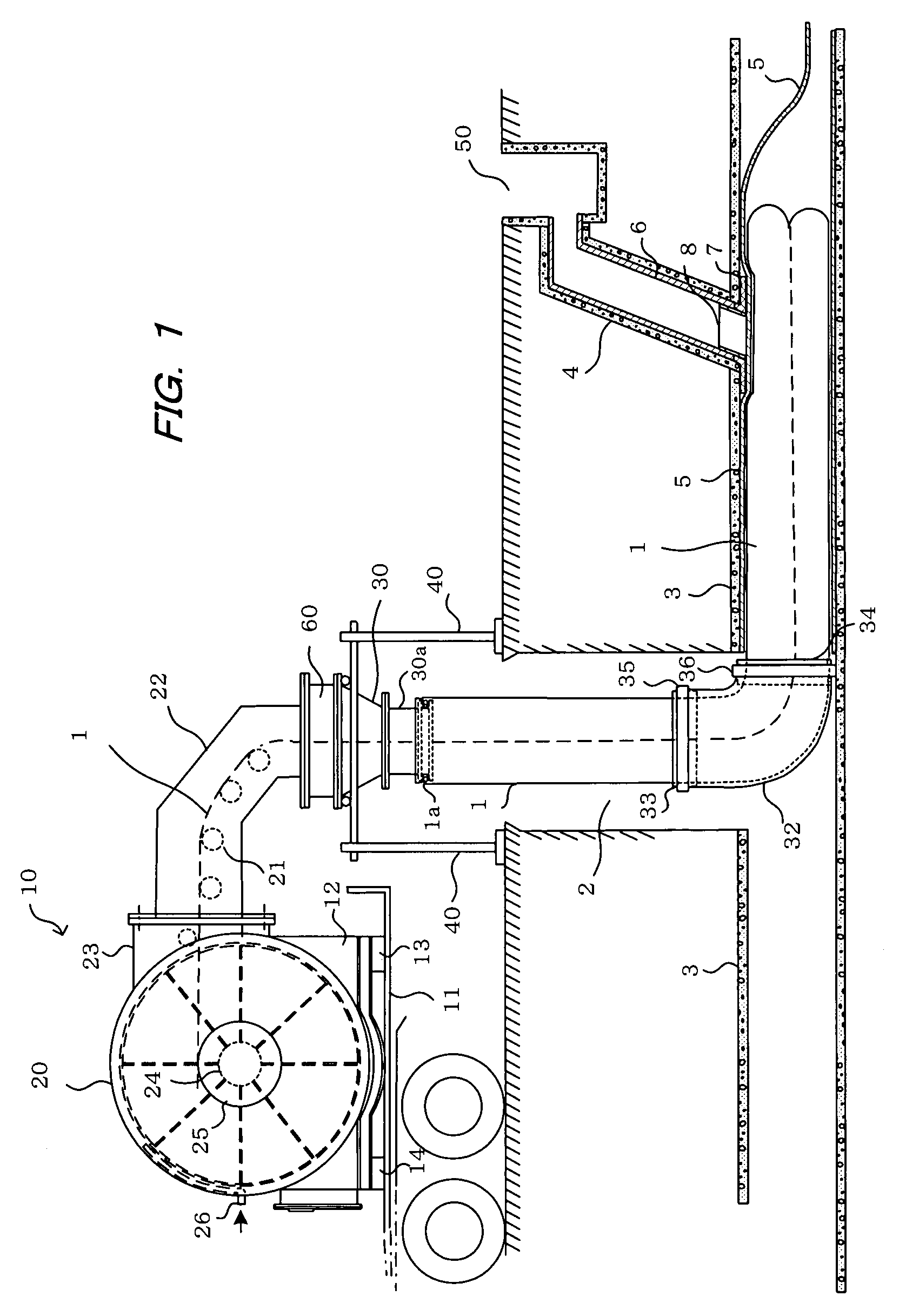
[0024]FIG. 1 show an everting apparatus 10 for everting a main pipe lining material 1 for lining a sewer pipe or other main pipe 3 and a start liner 5. The everting apparatus 10 is mounted on a load platform of a truck 11 via a support plate 12 and upper and lower regulatory mechanisms 13, 14, and is transported to a construction site having a manhole 2. The everting apparatus 10 has a receptacle 20 having an airtight closed structure for accommodating the start liner 5 and the main pipe lining material 1, which is connected to a terminal end of the start liner. A mounting pipe 60 is detachably mounted to the receptacle 20 via a guide part 22 having a plurality of guide rollers 21. A cylindrical eversion nozzle 30 having an opening 30a formed at a distal end is detachably mounted to the mounting pipe 60 so as to face the manhole 2.

[0025]A heating medium supplying hose,...


PUM

PropertyMeasurementUnit
anglesaaaaaaaaaa
pressureaaaaaaaaaa
shapeaaaaaaaaaa

Abstract

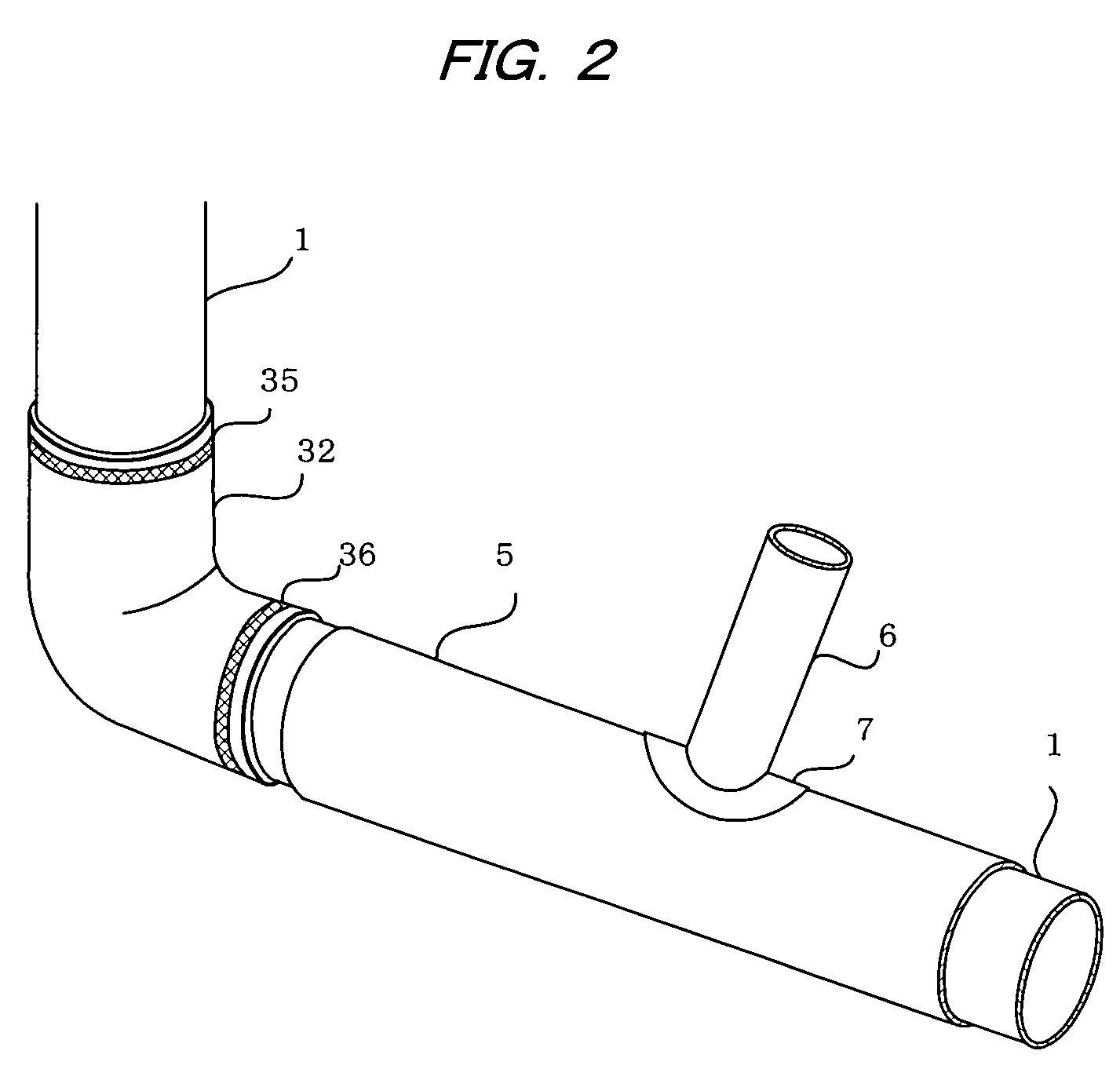
There is provided a pipe lining method wherein a lateral pipe lining material and a main pipe lining material are securely joined. After a lateral pipe has been lined, a start liner is applied to the main pipe and a main pipe lining material is then inserted. A heating wire for melting the start liner is mounted on a surface of a flange of the lateral pipe lining material during or after lining of the lateral pipe. While the main pipe is being lined, the heating wire is heated to melt the start liner existing between the flange of the lateral pipe lining material and the main pipe lining material. When the resin in the main pipe lining material is cured, the main pipe lining material and flange of the lateral pipe lining material are integrated. This allows the lateral pipe lining material and main pipe lining material to be reliably joined.

Description

BACKGROUND OF THE INVENTION[0001]1. Field of the Invention[0002]The present invention relates to a pipe lining method, and more specifically relates to a pipe lining method in which, after a lateral pipe has been lined, a start liner is applied to a main pipe in order to line the main pipe.[0003]2. Description of the Prior Art[0004]A method for repairing pipes is known in which, when an underground sewer pipe or other pipe has degraded over time, the pipe is not extracted from the ground, but, instead, a lining is applied to an inner peripheral surface of the pipe to be repaired.[0005]In this method, a pipe lining material is obtained by impregnating a tubular non-woven cloth, whose outer peripheral surface is covered by a highly airtight film, with a curable resin. The tubular pipe lining material is inserted into the pipe while being everted by fluid pressure, and then pressed against the inner peripheral surface of the pipe. The curable resin impregnated in the pipe lining materi...

Claims


Application Information

Patent Timeline
Patent Type & Authority Patents(United States)
IPC IPC(8): F16L55/16
CPCF16L55/179B29C63/0086B29C63/36F16L55/1651
Inventor KAMIYAMA, TAKAOKANETA, KOJIFUJII, KENJI
Owner SHONAN GOSEI JUSHI SEISAKUSHO KK
Learn More