
Process for creating a parametric surface having a required geometrical continuity

a parametric surface and continuity technology, applied in the field of computer-aided design, can solve the problems of insufficient continuity quality and not widely accepted subdivision surfaces, and achieve the effect of facilitating the resolution of equations

Active Publication Date: 2008-07-15
DASSAULT SYSTEMES
View PDF5 Cites 30 Cited by
  • Summary
  • Abstract
  • Description
  • Claims
  • Application Information

AI Technical Summary

Benefits of technology

The process effectively achieves the required geometrical continuity, such as G2 continuity, while being compatible with both open and closed vertices, simplifying the creation of smooth surfaces and maintaining the initial topology of the base mesh.

Problems solved by technology

An important issue in using patches is that patches must be adequately joined to ensure geometric continuity along the patch boundaries.
However, in the field of CAD, subdivision surfaces are not commonly accepted as they are not parametric.
Nevertheless, the resulting parametric surfaces give rise to an insufficient quality of continuity.
However, this approach does manifestly apply to closed extraordinary vertices only.

Method used


Image

  • Process for creating a parametric surface having a required geometrical continuity
  • Process for creating a parametric surface having a required geometrical continuity
  • Process for creating a parametric surface having a required geometrical continuity

Examples


Embodiment Construction

[0050]The invention is directed to a process likely to be implemented by a CAD software. User can control the process through a graphical user interface (or GUI) that may be a typical CAD interface, having usual menu bars as well as bottom and side toolbars. Such menu- and toolbars contain a set of user-selectable icons, each icon being associated with one or more operations or functions, as known in the art.

[0051]Some of these icons are associated with software tools, adapted for editing and / or representing a modeled object. The software tools in question are further possibly grouped in workbenches. Otherwise put, each workbench comprises a different subset of software tools. In particular, one of these is an edition workbench, suitable for editing geometrical features of the modeled object. In operation, a designer may for example pre-select a part of the object and then initiate an operation (e.g. change the shape, dimension, color, etc.) by selecting an appropriate icon and actu...


PUM


Abstract

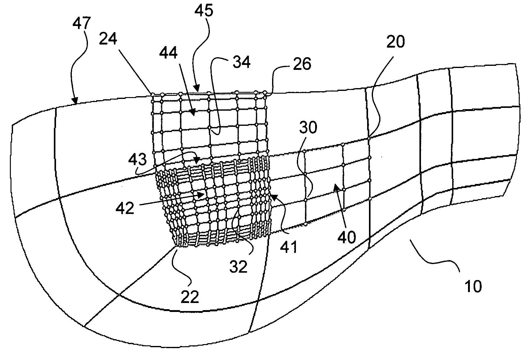
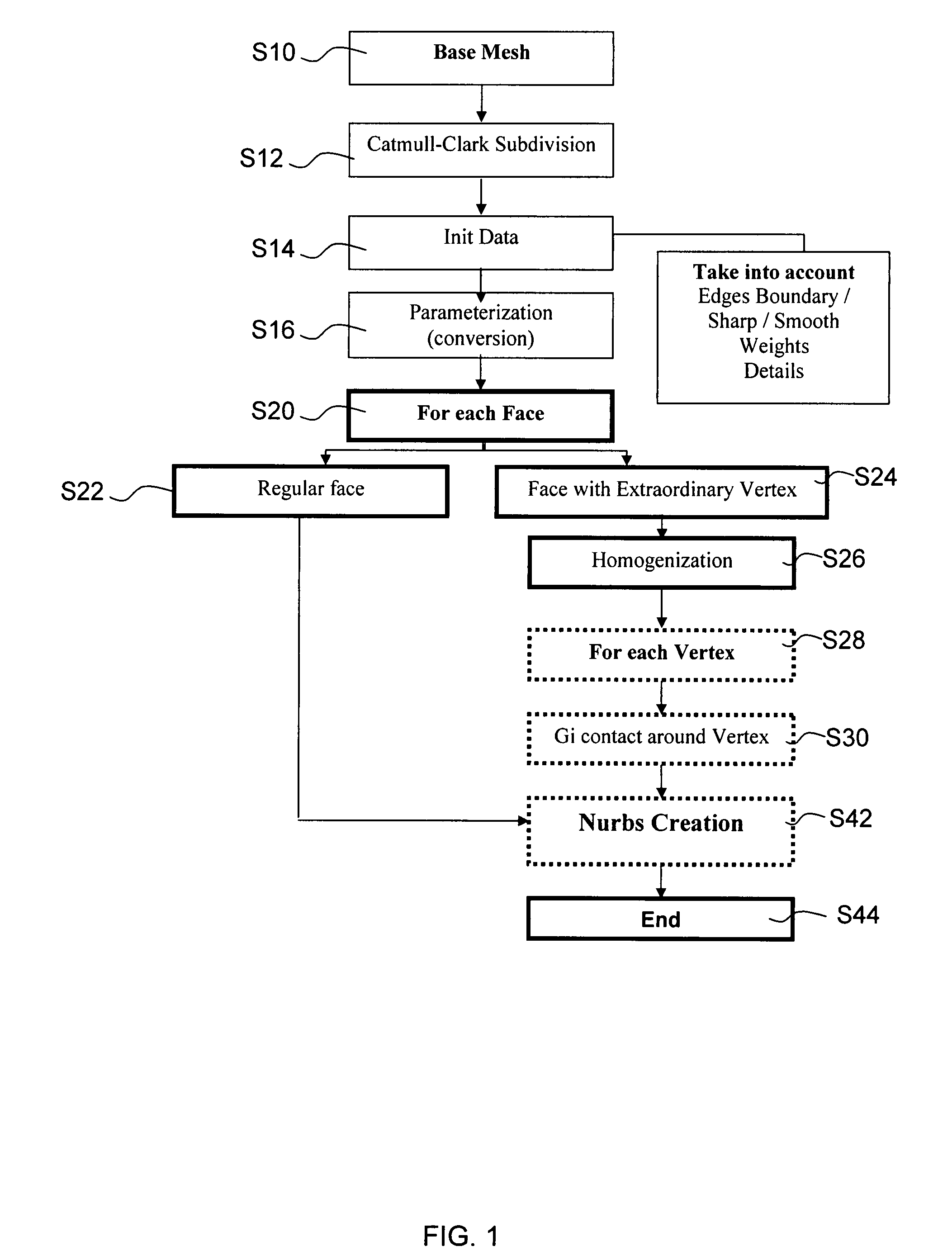
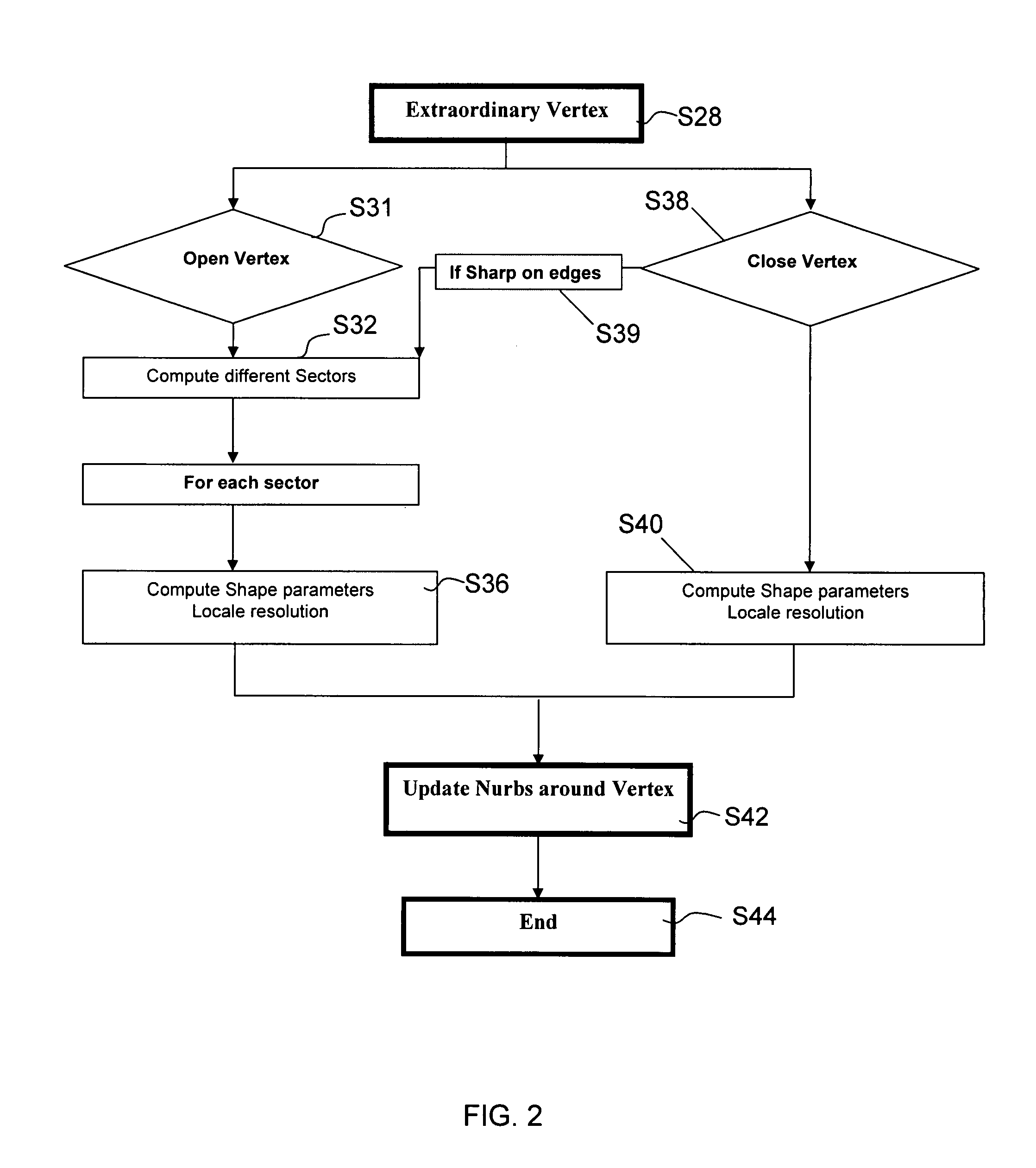
Creating a parametric surface having a required geometrical continuity Gi from a set of parametric elementary surfaces includes providing a set of parametric elementary surfaces, each elementary surface having edges, with vertices joining adjacent edges, each elementary surface having an internal continuity Cj at least equal to the required continuity Gi, the geometrical continuity between at least two elementary surfaces across their common edge being less than the required continuity Gi. For each singular vertex, the process can include defining a system of equations linking the parameters (including control points) of the parametric elementary surfaces across edges joined to the vertex and enforcing the required geometrical continuity across the joined edges and solving the system of equations to obtain the parameters.

Description

FIELD OF THE INVENTION[0001]The invention relates to the field of computer-aided design, and more specifically to computer-aided creation of parametric surfaces.BACKGROUND OF THE INVENTION[0002]A number of systems and programs are offered on the market for the design of parts or assemblies of parts, such as the one provided by the applicant under the trademark CATIA. These so-called computer-aided design (CAD) systems allow a user to construct and manipulate complex three-dimensional (3D) models of parts or assembly of parts.[0003]Creation of 3D computer graphics involves various steps, including modeling and process steps (subdivision of base meshes, conversion into parametric surfaces, rendering . . . ).[0004]A number of different modeling techniques can be used to create a model of an assembly. These techniques include solid modeling, wire-frame modeling, and surface modeling. Solid modeling techniques provide for topological 3D models, where the 3D model is a collection of inter...

Claims


Application Information

Patent Timeline
Patent Type & Authority Patents(United States)
IPC IPC(8): G06T17/00
CPCG06T17/30G06T17/20
Inventor NIGRO, VINCENT
Owner DASSAULT SYSTEMES
Learn More