
Method and system for automatically compensating for diagnosed banding defects prior to the performance of remedial service

a banding defect and automatic compensation technology, applied in the direction of instruments, electrographic process equipment, printing, etc., to achieve the effect of attenuating the banding defect and prolonging the operational effectiveness of the image reproduction machin

Inactive Publication Date: 2008-07-15
XEROX CORP
View PDF31 Cites 8 Cited by
  • Summary
  • Abstract
  • Description
  • Claims
  • Application Information

AI Technical Summary

Benefits of technology

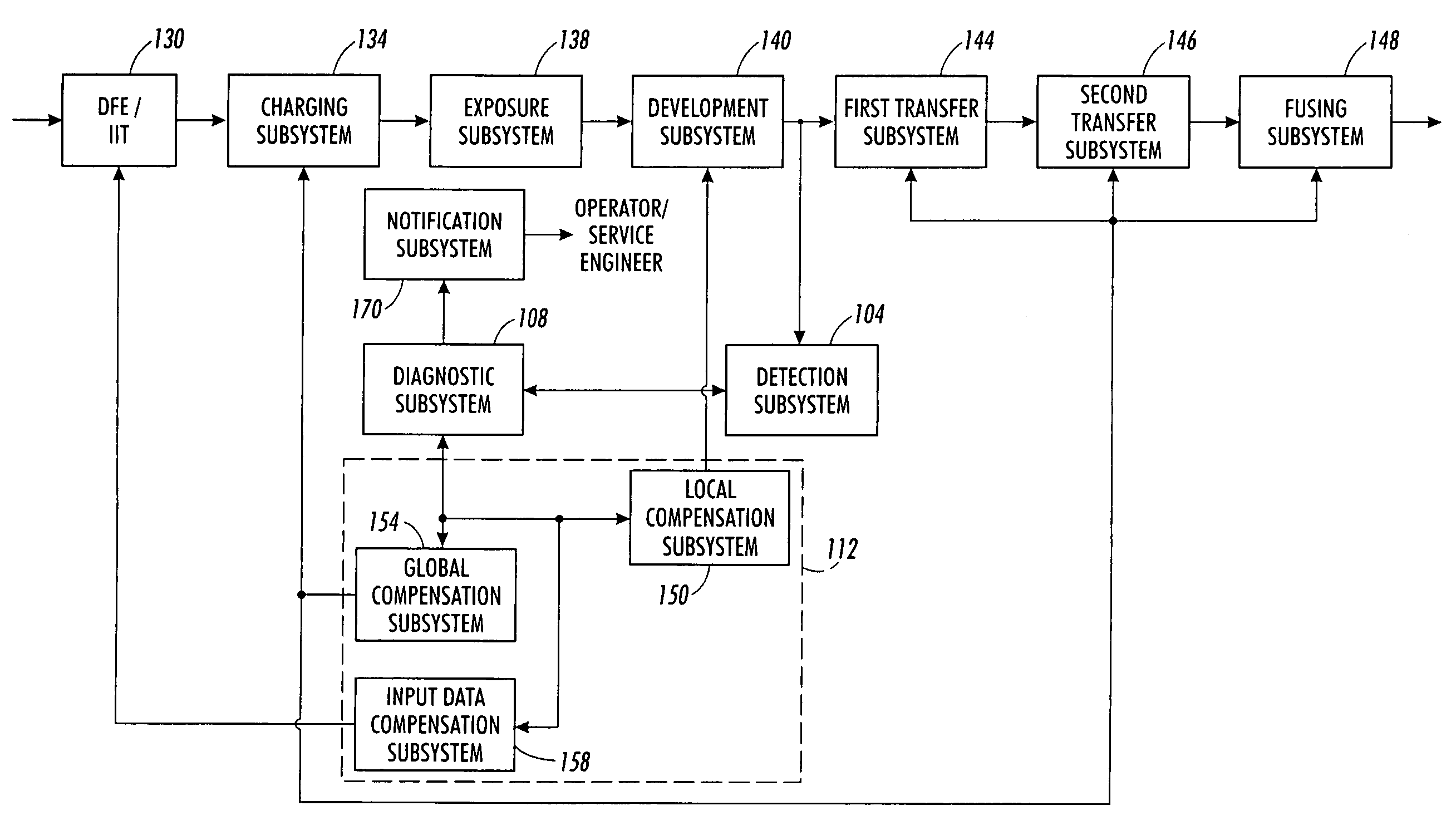
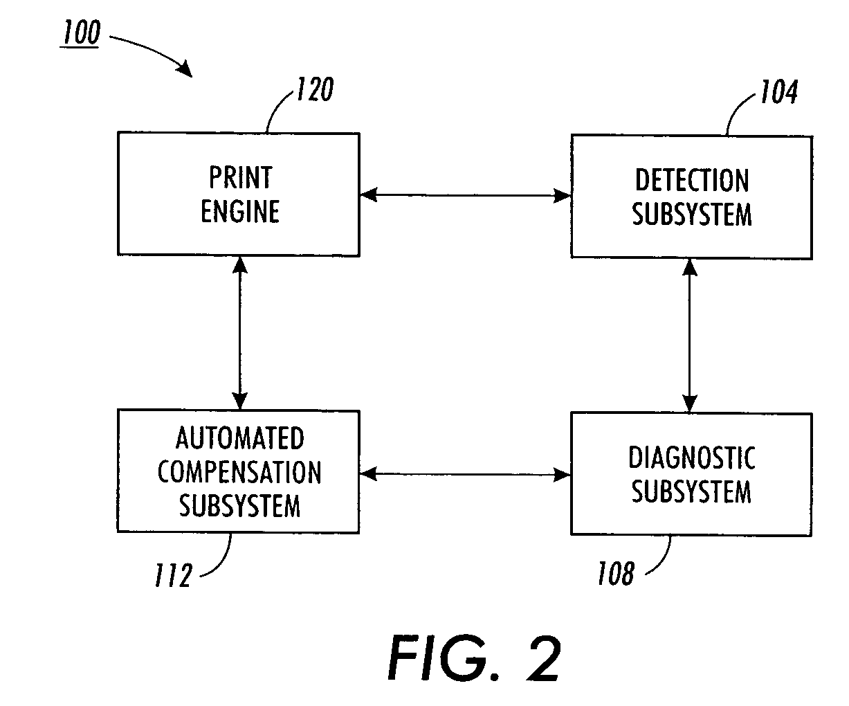
The present invention addresses the need for extending the operational effectiveness of an image reproduction machine without requiring downtime for service by personnel. The invention includes a detection subsystem that monitors the image reproduction system for banding defects and a compensation subsystem that automatically adjusts the system components to compensate for the detected defects. The detection subsystem may monitor various components of the system, such as the photoreceptor belt, charge subsystem, exposure subsystem, development subsystem, and toner density on the photoreceptor belt. The compensation subsystem may adjust system components, such as the charging system, to continue the operation of the image reproduction system. The detection subsystem may also monitor the residual toner density on the photoreceptor belt, transfer subsystem, or intermediate belt. The invention allows for the detection and correction of banding defects in real-time, improving the quality of the produced images.

Problems solved by technology

The charging errors may be provided by the detection subsystem to the compensation system so that system component adjustments may occur for continuing the operation of the image reproduction system.

Method used


Image

  • Method and system for automatically compensating for diagnosed banding defects prior to the performance of remedial service
  • Method and system for automatically compensating for diagnosed banding defects prior to the performance of remedial service
  • Method and system for automatically compensating for diagnosed banding defects prior to the performance of remedial service

Examples


Embodiment Construction

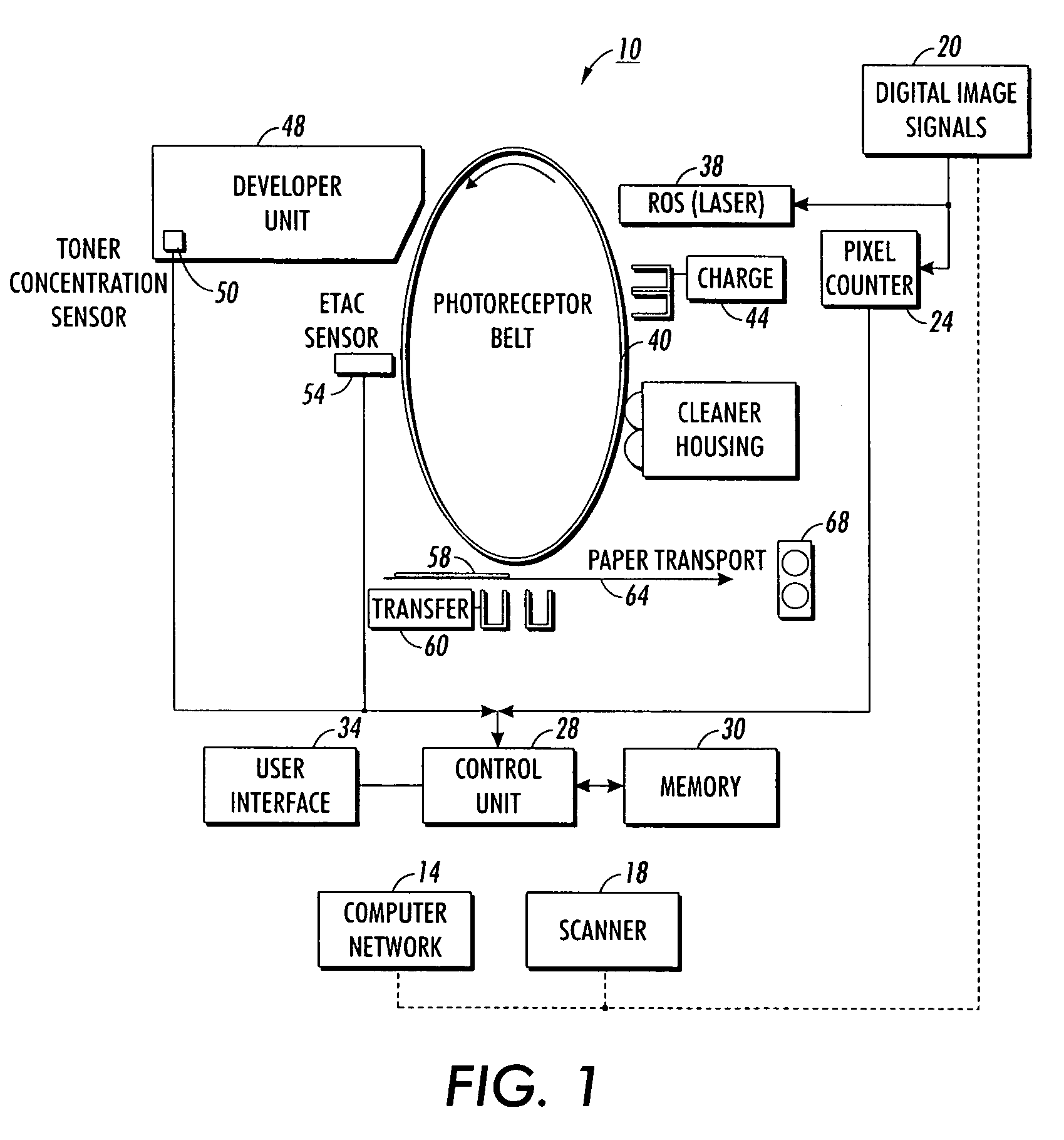
[0038]FIG. 1 shows a digital document reproduction system in which the calibration of the present invention may be used. The system 10 may include a computer network 14 through which digital documents are received from computers, scanners, and other digital document generators. Also, digital document generators, such as scanner 18, may be coupled to the digital image receiver 20. The data of the digital document images are provided to a pixel counter 24 that is also coupled to a controller 28 having a memory 30 and a user interface 34. The digital document image data is also used to drive the raster output scanner 38. The photoreceptor belt 40 rotates in the direction shown in FIG. 1 for the development of the latent image and the transfer of toner from the latent image to the support material. The system shown in FIG. 1 may also include an intermediate belt for the transfer of toners from the photoreceptor to the sheet medium. A system of the present invention, discussed in more de...


PUM


Abstract

A system that extends the operational effectiveness of an image reproduction machine without requiring downtime for service by personnel includes a detection subsystem that monitors components of an image reproduction system for detecting a banding defect in the image reproduction system and an automated compensation subsystem for modifying operation of the image reproduction system to compensate for the detected banding defect so that the image reproduction system continues to generate images at an acceptable quality level. The automated compensation subsystem adjusts components and / or data used by image reproduction system to compensate for the identified banding defect without requiring immediate operator or service personnel intervention. This compensation may successfully attenuate the banding defect so that the image reproduction system continues to produce acceptable images without downtime while awaiting service by personnel. The system may also include a diagnostic subsystem for determining causes for a detected banding defect to further enhance the operation of the compensation system or to facilitate a repair action by a person.

Description

FIELD OF THE INVENTION[0001]The present invention relates generally to diagnostic systems for identifying banding defects in digital image reproduction systems, and more particularly, to such diagnostic systems that prescribe a corrective action to remedy the identified banding defect.BACKGROUND OF THE INVENTION[0002]Digital image reproduction systems are well-known. These systems typically include a digital document generator that may be coupled to the reproduction system directly or through a computer network. Digital document generators include computers, scanners, or other devices that store or permit a user to define content for a digital document. The digital data are provided to a print engine so the controller of the engine may control the process. The reproduction system also includes a photoreceptor belt or drum that provides a rotating surface for the exposure, development, and transfer of a latent image that corresponds to the digital document.[0003]The latent image expo...

Claims


Application Information

Patent Timeline
Patent Type & Authority Patents(United States)
IPC IPC(8): B41J2/47
CPCG03G15/50G03G15/00G06Q50/04G06Q50/10
Inventor SAMPATH, MEERAMIZES, HOWARD A.ZOLTNER, SUSAN
Owner XEROX CORP
Learn More