Object tracking method and object tracking apparatus

a technology of object tracking and object tracking, which is applied in the field of object tracking system, can solve the problems of inability to guarantee the accurate tracking of the intruding object to be tracked, the inability to maintain steady tracking of the intruding object, and the inability to maintain steady tracking

Inactive Publication Date: 2008-07-15
KOKUSA ELECTRIC CO LTD
View PDF13 Cites 24 Cited by
  • Summary
  • Abstract
  • Description
  • Claims
  • Application Information

AI Technical Summary

Benefits of technology

[0032]Then, the template is updated to the template 905a at time point t1+1 and to the template 907a at time point t1+2. After this process is repeated up to time point t1+3, the template, that held the front portion of the vehicle with the head lights when the tracking started at time point t1−1, now holds the left side of the vehicle at time point t1+3. This phenomenon is caused by the fact that the matching is conducted in such a manner as to reduce the displacement between the input image handled by template matching and the high-contrast portion of the template image, i.e. the head lights of the vehicle in this case. As a result, as shown in FIG. 7, the template is displaced leftward when the intruding object turns from right to left, and rightward when it turns from left to right.
[0036]Another object of the invention is to provide an object tracking method and an object tracking apparatus which operates reliably and stably to detect and track an intruding object accurately even in the case where the intruding object changes its direction considerably.
[0040]In an example of this aspect of the invention, the image change area detection step is to detect a change area of the image signal by comparing the two frames of image signals picked up at different time points by the imaging unit while the camera universal head (imaging unit controller) is stationary. In another example of this aspect of the invention, the object position correcting step is to enlarge the intended area in steps for accurate position detection of an intruding object based on the intruding object position information and to correct the intruding object position information by detecting the change area of the image signal obtained in the image signal change area detection step and the accurate position of the intruding object based on the intended area.
[0045]According to this invention, the employment of the inter-frame difference processing step obviates the problems of the prior art in which the template may be displaced with respect to an intruding object and come to contain many images other than the intruding object in the case where the intruding object changes its direction, with the result that the template matches with the background contained therein and the image of the intruding object cannot be caught. Further, even an intruding object considerably changing its direction can be detected and tracked accurately.

Problems solved by technology

Thus, the method of tracking an intruding object using the template matching has the disadvantage that in the case where the intruding object changes its direction, the pattern of the intruding object apparently moves and displaces the template position from the position of the intruding object.
As a result, the accurate tracking of the intruding object to be tracked cannot be guaranteed and the steady tracking of the intruding object becomes impossible.
As described above, the prior art has the disadvantage that steady tracking becomes impossible in the case where an intruding object changes its direction considerably.

Method used


Image

  • Object tracking method and object tracking apparatus
  • Object tracking method and object tracking apparatus
  • Object tracking method and object tracking apparatus

Examples


first embodiment

[0092]The processing shown in FIG. 3 is a combination of the processing of FIG. 2 and the conventional intruding object tracking method using the template matching shown in FIG. 5. In this combined processing, the steps other than the difference amount determining step 113 and the intruding object stop determining step 116 are already explained and therefore not explained below. Since the maximum difference amount position search step 112 in this embodiment is slightly different from that of the first embodiment shown in FIG. 2, the maximum difference amount position search step 112 in this embodiment will be explained later with reference to FIGS. 8A to 8E.

[0093]In this process, the position of the intruding object is detected by template matching through the process from the template matching step 106 to the first intruding object position correcting step 108. In view of the likelihood of the detected intruding object position being displaced from the template position as in the p...

second embodiment

[0098]The flow of this processing is explained with reference to FIG. 9. FIG. 9 is a diagram showing an example of the process executed according to the invention and represents a case in which a vehicle running along a curved vehicle lane in the imaging field of view shown in FIG. 7 is tracked as an intruding object.

[0099]FIG. 9 shows a case where the camera universal head is not controlled in order to explain the effects of the inter-frame difference processing step 110 and the maximum difference amount position search step 112. The operation timings of the camera universal head control processing and the inter-frame difference processing will be explained later.

[0100]Numerals 1101, 1103, 1105 and 1107 designate the template image at time points t1−1, t1, t1+1 and t1+2, respectively, and numerals 1101a, 1103a, 1105a and 1107a the template at time points t1−1, t1, t1+1 and t1+2, respectively. Also, numerals 1102, 1104, 1106 and 1108 designate input images at time points t1, t1+1 an...

third embodiment

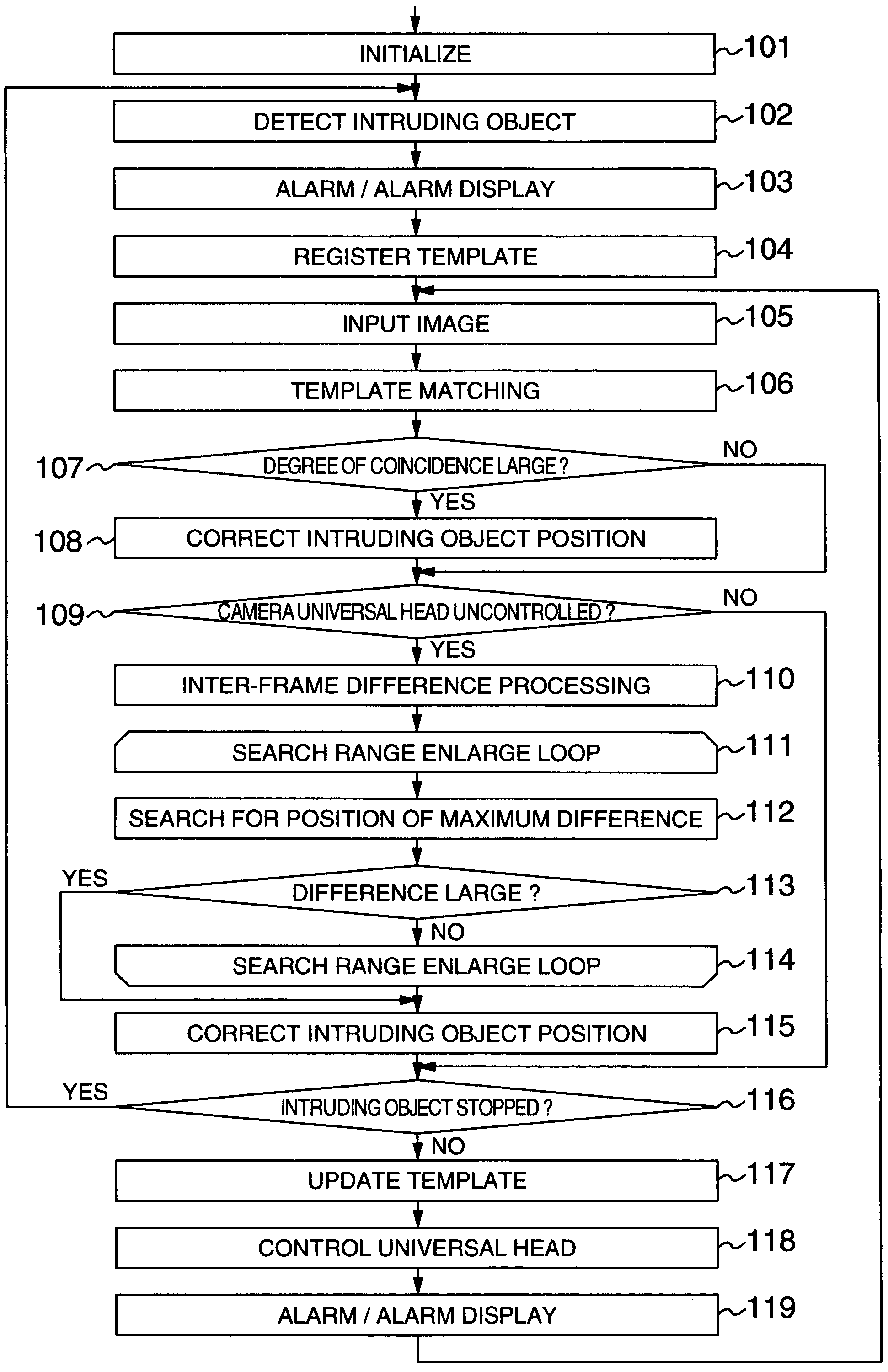
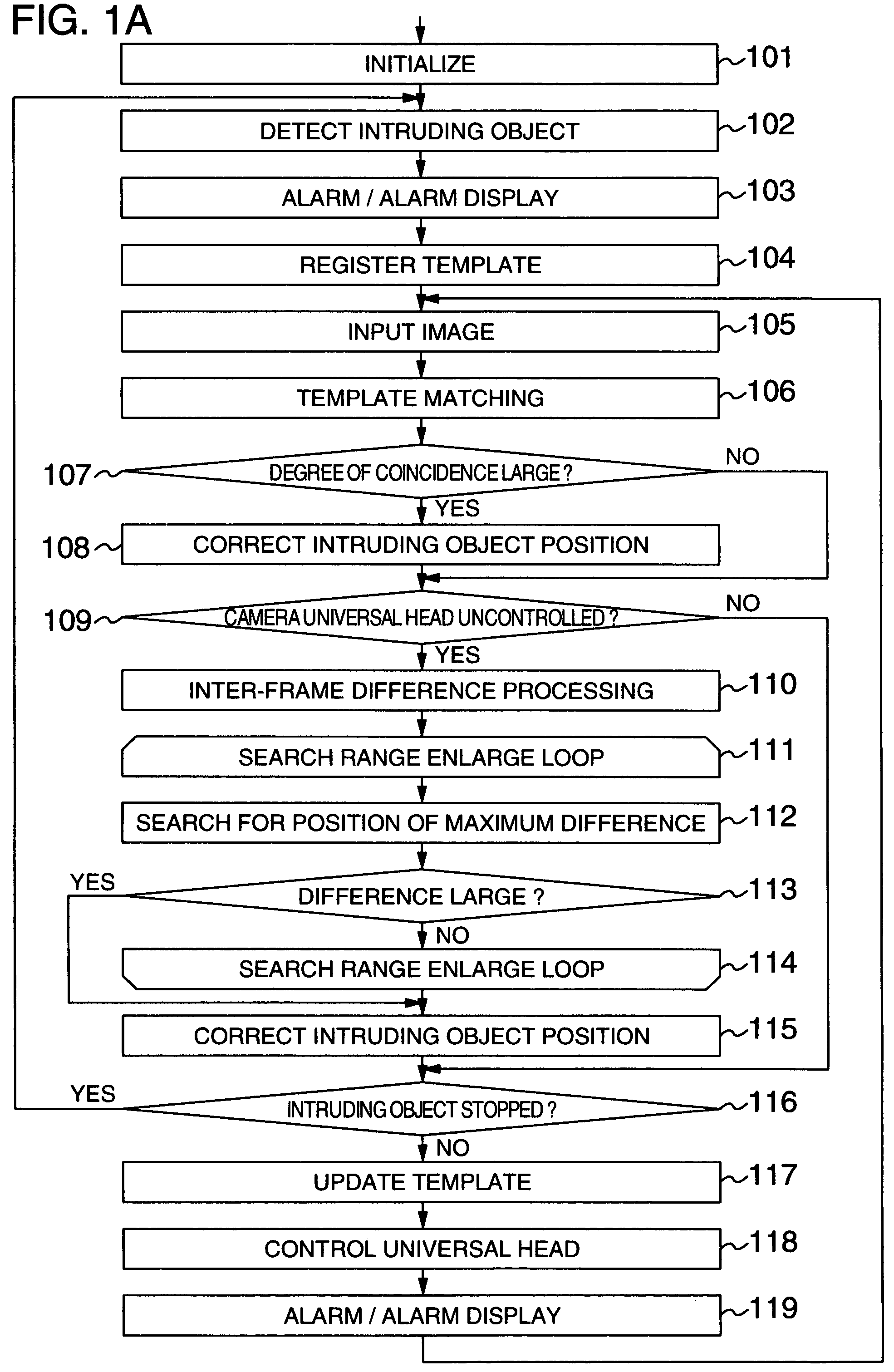
[0112]The operation of the invention is explained with reference to FIGS. 1A and 1B. FIGS. 1A and 1B are flowcharts showing an example of the processing according to the third-embodiment of the invention. The processing shown in FIG. 1A is equivalent to the process of FIG. 3 with the search range enlarging loop (steps 111 to 114) added thereto. The other processing steps have already been explained and are not explained again.

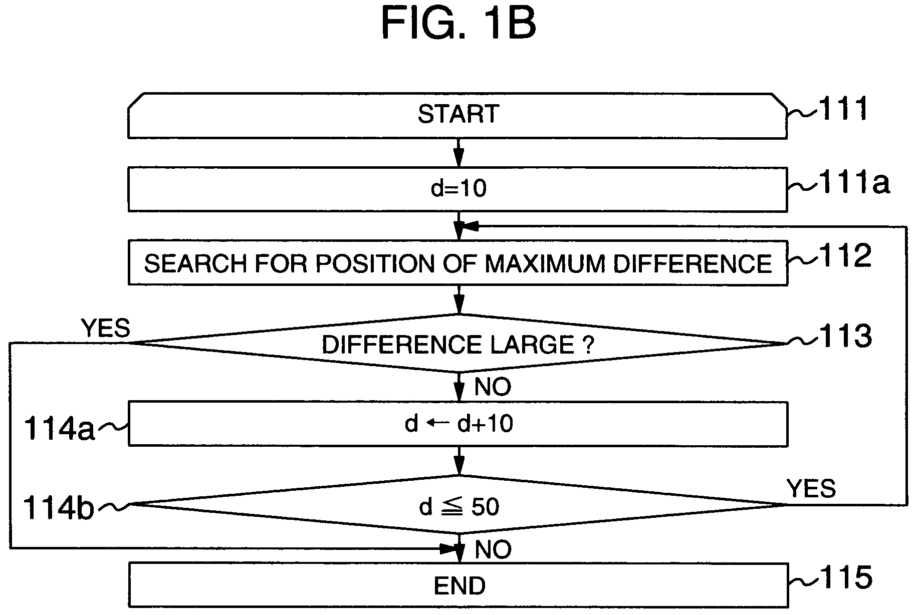
[0113]FIG. 1B is a flowchart showing the detail of the search range enlarging process (steps 112 to 114).

[0114]The search range enlarging loop (steps 111 to 114) is such that the search area 1003b providing the projection range of the difference image due to the inter-frame difference shown in FIG. 8C is enlarged in steps (in five steps in this case). According to this embodiment, the search range enlarging process (steps 111 to 114) is repeated a plurality of times or, say, five times for each processing frame. In the second embodiment described above, the pro...


PUM


Abstract

An object tracking method and an object tracking apparatus. Based on two or more frames of images acquired at different time points from an imaging unit, an image changing area is detected between the frames. Based on the image changing area thus detected, the position of an object is detected. The detected position of the object is set as a new detected position of the object in place of the present detected position of the object, thereby detecting and tracking an object intruding into a monitor area.

Description

CROSS-REFERENCE TO RELATED APPLICATION[0001]The present invention is related to U.S. patent application Ser. No. 09 / 592,996 filed Jun. 13, 2000, now U.S. Pat. No. 6,687,386, entitled “OBJECT TRACKING METHOD AND OBJECT TRACKING APPARATUS”, the entire content of which is incorporated herein by reference for all purposes.BACKGROUND OF THE INVENTION[0002]The present invention relates to an object tracking system using an imaging unit, or in particular to an object tracking method and an object tracking apparatus for automatically detecting an object within a monitor area by processing an image signal and tracking the object by controlling the universal head of the camera carrying the imaging unit.[0003]An object tracking system such as a remote monitor system using an imaging unit (hereinafter referred to as “the camera”) such as a TV camera has been widely used. Many of them are what is called a manned monitor system which is operated by a monitor person watching the image displayed on...

Claims


Application Information

Patent Timeline
Patent Type & Authority Patents(United States)
IPC IPC(8): H04N7/18G01S3/786G06T7/20G06V10/24
CPCG01S3/7864G06K9/00771G06K9/00785G06K9/32H04N7/183G06T7/2053G06T7/204G06T2207/10016G06T2207/30232G06T7/248G06T7/254G06V20/54G06V20/52G06V10/24
Inventor ITO, WATARUUEDA, HIROTADA
Owner KOKUSA ELECTRIC CO LTD
Why Eureka
Try Eureka