Tunable and aimable artificial lightening producing device

a production device and tunable technology, applied in the direction of weapons, electrical devices, defence devices, etc., can solve the problems of not teaching a tunable and aimable artificial lightening producing device, and not being suitabl

Inactive Publication Date: 2008-07-15
BITAR PETER V
View PDF5 Cites 25 Cited by
  • Summary
  • Abstract
  • Description
  • Claims
  • Application Information

AI Technical Summary

Benefits of technology

[0011]ACCORDINGLY, AN OBJECT of the present invention is to provide a tunable and aimable artificial lightening producing device that avoids the disadvantages of the prior art.

Problems solved by technology

Even though these innovations may be suitable for the specific individual purposes to which they address, however, they differ from the present invention in that they do not teach a tunable and aimable artificial lightening producing device.
Furthermore, even though these innovations may be suitable for the specific individual purposes to which they address, however, they would not be suitable for the purposes of the present invention as heretofore described, namely, a tunable and aimable artificial lightening producing device.

Method used


Image

  • Tunable and aimable artificial lightening producing device
  • Tunable and aimable artificial lightening producing device
  • Tunable and aimable artificial lightening producing device

Examples


first embodiment

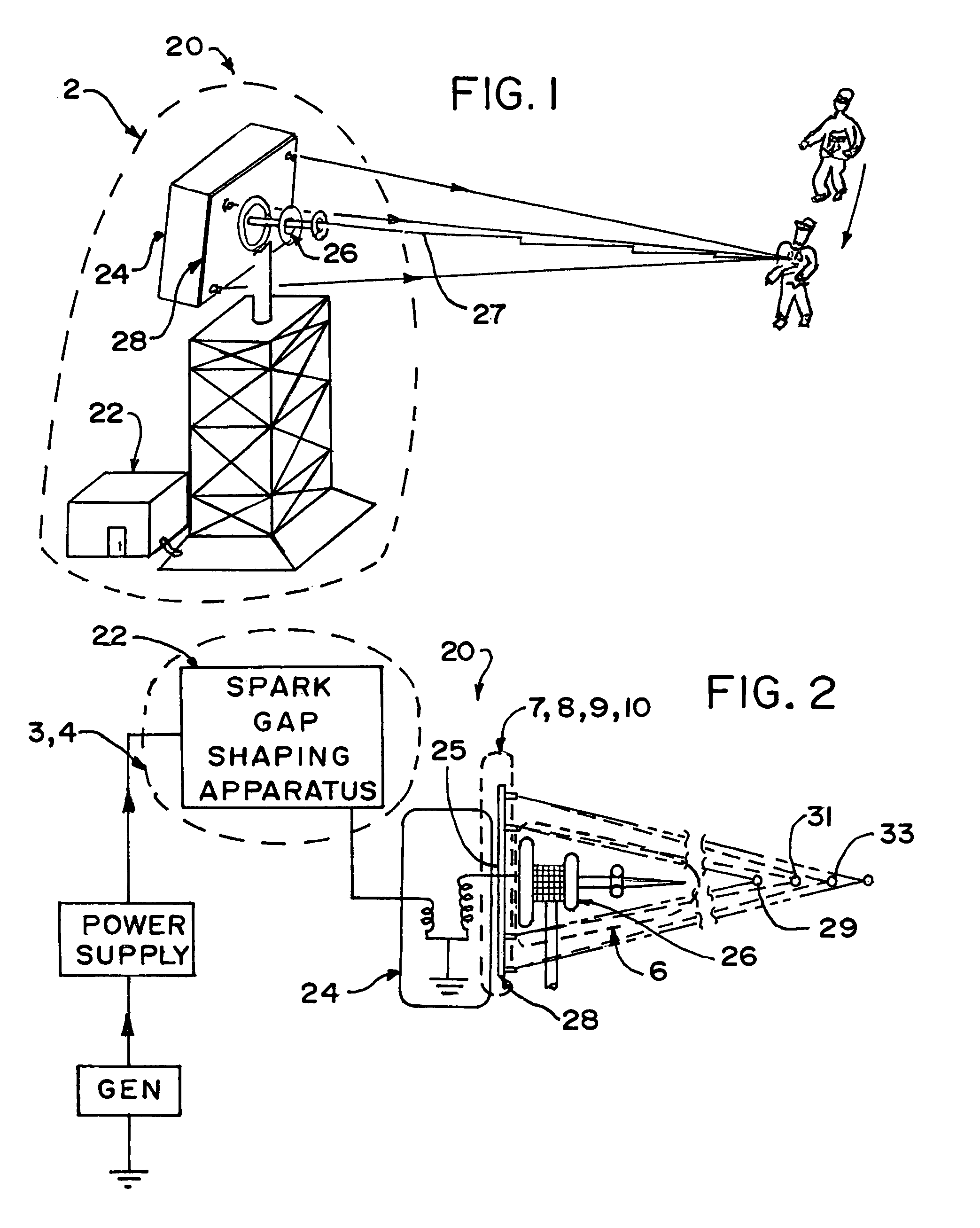
[0129]a second stage directionalizer 128 can best be seen in FIG. 7, which is a diagrammatic side elevational view of the area generally enclosed by the dotted curve identified by ARROW 7 in FIG. 2 of a first embodiment of the second stage directionalizer of the tunable and aimable artificial lightening producing device of the present invention, and as such, will be discussed with reference thereto.

[0130]The second stage directionalizer 128 comprises a plurality of lasers 162.

[0131]The plurality of lasers 162 of the second stage directionalizer 128 are operatively connected to each other and to a controller 164.

[0132]The controller 164 of the second stage directionalizer 128 causes the plurality of lasers 162 of the second stage directionalizer 128 to pivot in concert to cause convergence of beams 166 generated by the plurality of lasers 162 of the second stage directionalizer 128.

[0133]The second embodiment of the second stage directionalizer 228 can best be seen in FIG. 8, which i...

third embodiment

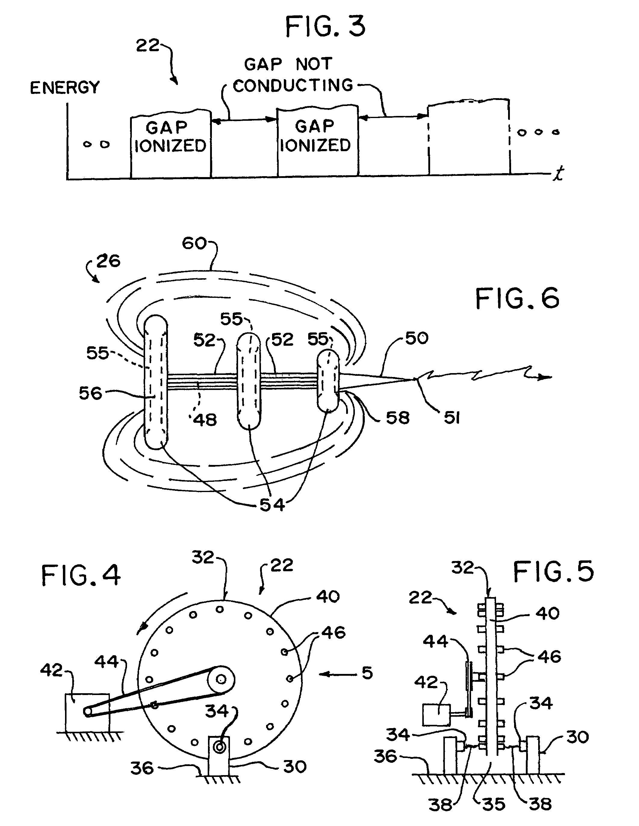
[0137]a second stage directionalizer 328 can best be seen in FIG. 9, which is a diagrammatic side elevational view of the area generally enclosed by the dotted curve identified by ARROW 9 in FIG. 2 of a third embodiment of the second stage directionalizer of the tunable and aimable artificial lightening producing device of the present invention, and as such, will be discussed with reference thereto.

[0138]The second stage directionalizer 328 comprises a plurality of lasers 362 and a plurality of mirrors 363.

[0139]The plurality of mirrors 363 of the second stage directionalizer 328 are operatively connected to each other and to a controller 364.

[0140]The controller 364 of the second stage directionalizer 328 causes the plurality of mirrors 363 of the second stage directionalizer 328 to pivot in concert and cause convergence of beams 366 generated by the plurality of lasers 362 of the second stage directionalizer 328.

[0141]A fourth embodiment of a second stage directionalizer 428 can b...


PUM


Abstract

A tunable and aimable artificial lightning producing device for tetanizing human voluntary muscle, disabling vehicular electronic ignition systems, and for pre-detonating wired explosives. A spark gap shaping apparatus controls a spark generated by a Tesla coil. A first stage directionalizer warps a normally spherical plasma field from the Tesla coil into an oval plasma field for confining the spark to within that shape. A second stage directionalizer converges multiple beams to successive points just ahead of a plasma field created by the first stage directionalizer without ionizing the beams, thereby maintaining ionization of a path of the spark. The spark is progressively arced to these points, thereby maintaining the path of the spark.

Description

BACKGROUND OF THE INVENTION[0001]1. Field of the Invention[0002]The present invention relates to a lightening producing device, and more particularly, the present invention relates to a tunable and aimable artificial lightening producing device.[0003]2. Description of the Prior Art[0004]Numerous innovations for signal generating devices have been provided in the prior art that will be described. Even though these innovations may be suitable for the specific individual purposes to which they address, however, they differ from the present invention in that they do not teach a tunable and aimable artificial lightening producing device.[0005]A FIRST EXAMPLE, U.S. Pat. No. 4,148,321 to Wyss et al. teaches an apparatus and method for the treatment and active massage of muscles, the apparatus comprising a generator arrangement providing a modulated alternating current with a medium-frequency carrier having a frequency comprised between 3000 Hz and 100,000 Hz, and an adjustable low modulati...

Claims


Application Information

Patent Timeline
Patent Type & Authority Patents(United States)
IPC IPC(8): H01T23/00
CPCF41H11/12F41H13/005F41H13/0012
Inventor BITAR, PETER V.
Owner BITAR PETER V
Why Eureka
Try Eureka