Liner contact automatic teat dip applicator

a technology of automatic teat dip and applicator, which is applied in the field of teat dips, can solve the problems of limited teat coverag

Active Publication Date: 2008-07-22
GEA FARM TECH
View PDF36 Cites 64 Cited by
  • Summary
  • Abstract
  • Description
  • Claims
  • Application Information

AI Technical Summary

Benefits of technology

[0009]The dip conduit can be a hose that connects to a nozzle to direct dip into the liner head chamber. Preferably, the nozzle has a relatively small diameter opening to limit the amount of milk that might enter the nozzle and dip hose. Alternatively, a check valve could be used to prevent milk from entering the nozzle, hose, and teat dip manifold.

Problems solved by technology

Nonetheless, with such a system there may only be limited coverage of the teat.

Method used


Image

  • Liner contact automatic teat dip applicator
  • Liner contact automatic teat dip applicator
  • Liner contact automatic teat dip applicator

Examples


Embodiment Construction

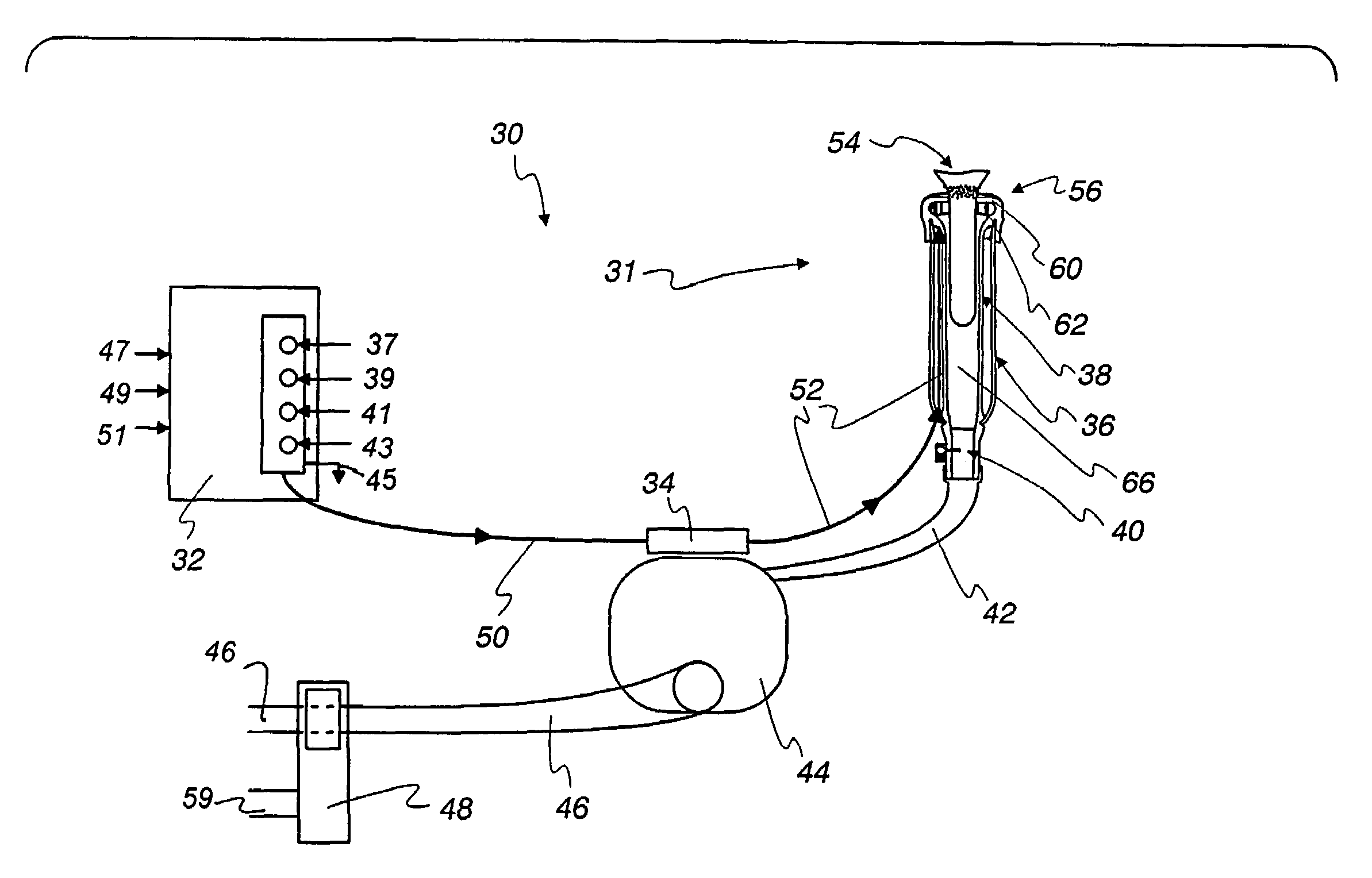
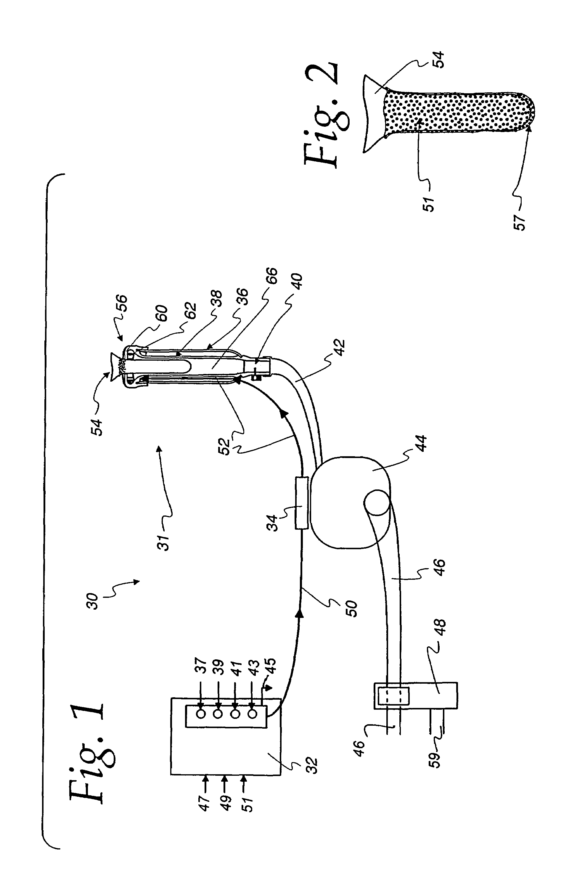
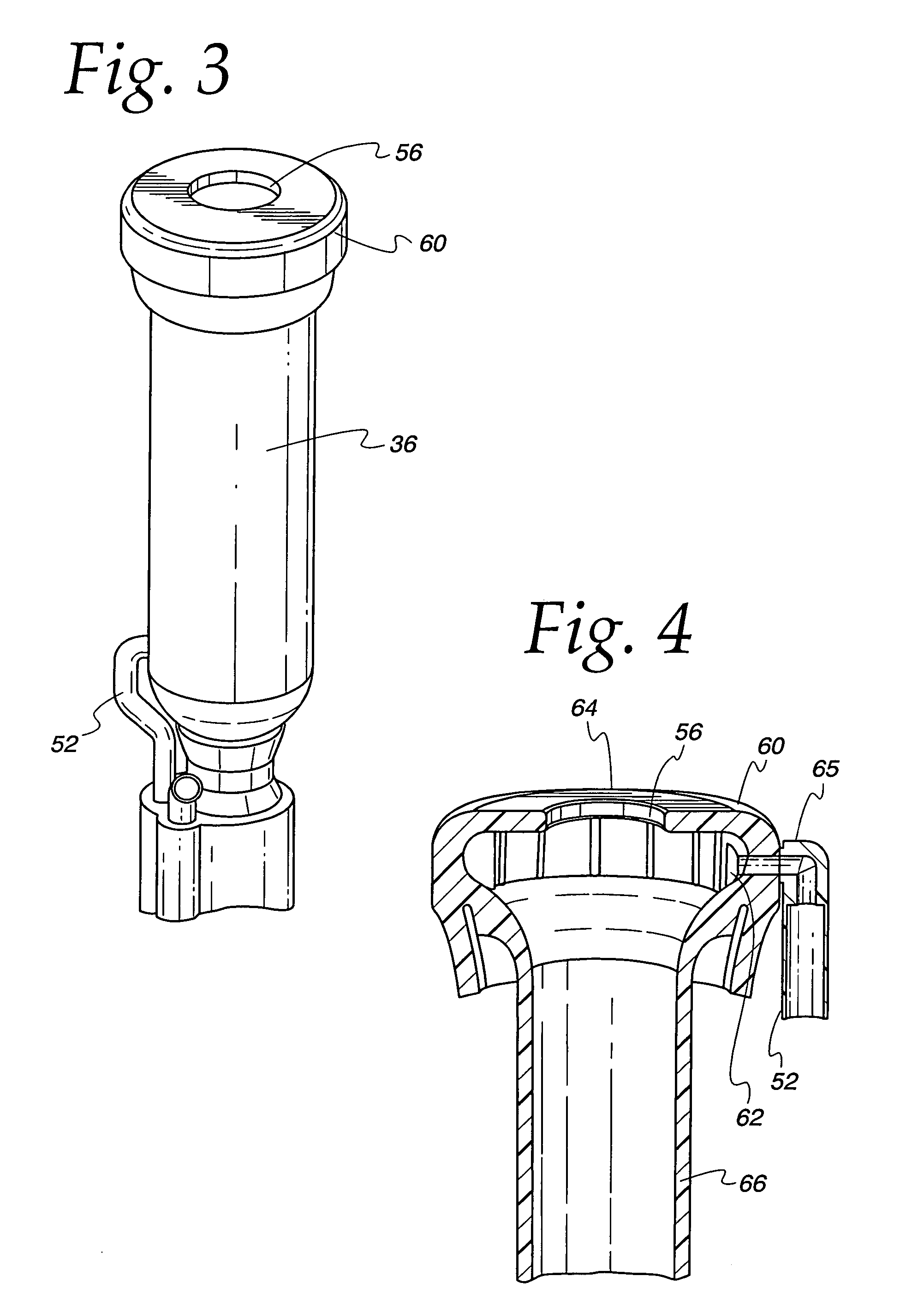
[0036]FIG. 1 illustrates a teat dip application system 30 in accordance with the present invention. The teat dip application system 30 includes an applicator 31 that applies dip to a cow or other dairy animal teat. The applicator 31 includes a control panel 32 and a dip manifold 34. A teat cup shell 36, a liner 38, a first backflush valve 40, a short milk tube 42, a milker unit 44, milk line 46, and an optional second backflush valve 48 are also provided to work as part of or in conjunction with the applicator 31.

[0037]The control panel 32 remotely controls operation of the teat dip application system 30. It can be automated with suitable manual overrides or it can be operated by manually engaging various control buttons in response to audible and / or visual signals reflecting the stage of a milking and backflush operation.

[0038]The control panel 32 controls the flow of air 37, water 39, teat dip 41, and any appropriate three-way valve 43 ventilation that may be necessary. A vent 45 ...


PUM


Abstract

A teat dip applicator and method direct a teat dip to a teat cup liner head that defines a chamber and nozzle through which teat dip flows to coat an animal teat prior to and during detachment of a milker unit from a dairy animal.

Description

[0001]This application is a continuation of Provisional Application No. 60 / 578,997 filed Jun. 12, 2004, the disclosure of which is incorporated herein by reference.BACKGROUND OF THE INVENTION[0002]This invention relates generally to teat dips for dairy animals and more particularly to methods and apparatus for applying teat dip to dairy animal teats and udders after milking and before detachment from a milker unit.[0003]After milking, a dairy animal's teats can be protected with a post-milking dip (“post-dip”) that protects the teats from infection. The post-dip is typically applied by an operator by dipping a liquid, spraying a liquid or applying a foam. This process is performed each time the animals are milked, and is generally useful in reducing the incidence of mastitis.[0004]One approach to simplifying this procedure is to apply the post-dip before the milker unit is detached as disclosed in WO 02 / 23976 A1, which is incorporated herein by reference. Nonetheless, with such a sy...

Claims


Application Information

Patent Timeline
Patent Type & Authority Patents(United States)
IPC IPC(8): A01J7/04
CPCA01J7/04
Inventor TORGERSON, KEVIN L.
Owner GEA FARM TECH
Why Eureka
Try Eureka