Battery device of vehicle power supply

a battery device and power supply technology, applied in the direction of electric devices, battery/fuel cell control arrangements, electric devices, etc., can solve the problems of reducing affecting the safety of the vehicle, and requiring a large amount of time and labor to mount the structure, so as to achieve convenient and efficient use, enhance safety, and ensure the effect of sufficient strength

Inactive Publication Date: 2008-07-22
SANYO ELECTRIC CO LTD
View PDF10 Cites 64 Cited by
  • Summary
  • Abstract
  • Description
  • Claims
  • Application Information

AI Technical Summary

Benefits of technology

[0009]The present invention has been developed in order to solve the aforementioned drawbacks. An important object of the present invention is to provide a power device for a vehicle which can reliably separate first and second cases fabricated with a division when a shock is caused by a crash, thus enhancing safety, and can firmly couple them when mounting them.
[0011]The power device described above has a feature that the first case and the second case are reliably separated during the shock caused by a crash, thus enhancing safety, and the first case and the second case are coupled to each other with a sufficient strength in a state of assembly into or mounting on a vehicle. The reason is that the power device couples the laminated portion of the first case and the second case with the shock breakdown pin to be broken by a shock. The shock breakdown pin penetrates and couples the laminated portion of the first case and the second case. With the coupling structure, when the shock of the crash is applied, the shock breakdown pin is cut or a head portion is deformed so that the shock breakdown pin slips out of a through hole penetrating through the first case and the second case, thereby separating the first case and the second case from each other. The shock breakdown pin is not broken in a state in which the shock of a crash, or the like, is not applied, and thus firmly couples the first case and the second case to each other. Therefore, a case obtained by coupling the first case and the second case through the shock breakdown pin can be mounted on a vehicle simply, easily and efficiently. Moreover, the coupling structure has a feature that the first case and the second case can be prevented from being separated from each other due to the vibration of the vehicle, or the like, in a state in which they are mounted on the vehicle, and can be firmly coupled to each other until a crash occurs. Furthermore, a coupling structure using the shock breakdown pin also has a feature that it can be prevented from deteriorating with the passage of time unlike an adhesive, and can firmly couple the first case to the second case for a long period of time.

Problems solved by technology

However, a great deal of time and labor is required to mount the structure in which the battery housing portion and the shock absorbing portion are separated from each other on the vehicle.
When the battery housing portion and the shock absorbing portion are coupled to one cover plate, an upper cover for example, they are reliably separated from each other during a shock caused by a crash; however, it is hard to guarantee a sufficient strength in a state of assembly into the vehicle and mounting on the vehicle.
In a state in which the vehicle does not crash, however, it is hard to prevent the coupling portion from causing the separation.

Method used


Image

  • Battery device of vehicle power supply
  • Battery device of vehicle power supply
  • Battery device of vehicle power supply

Examples


Embodiment Construction

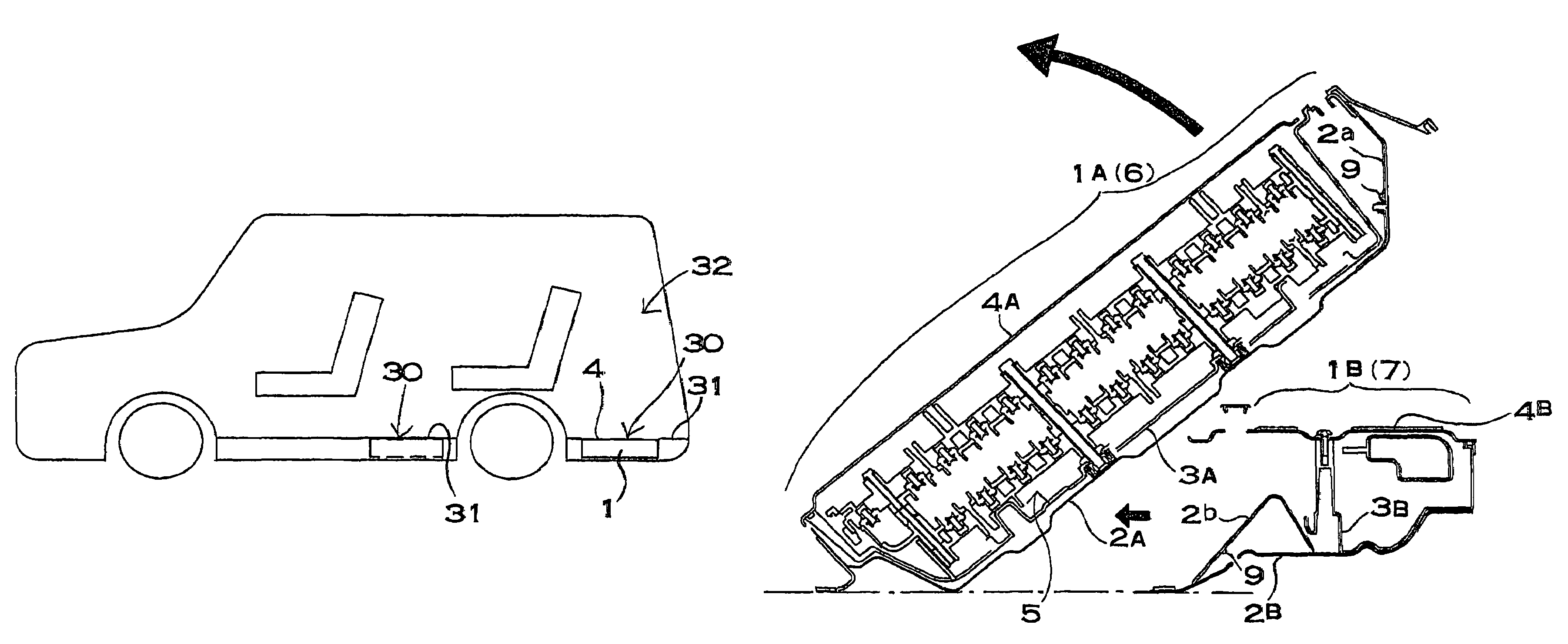
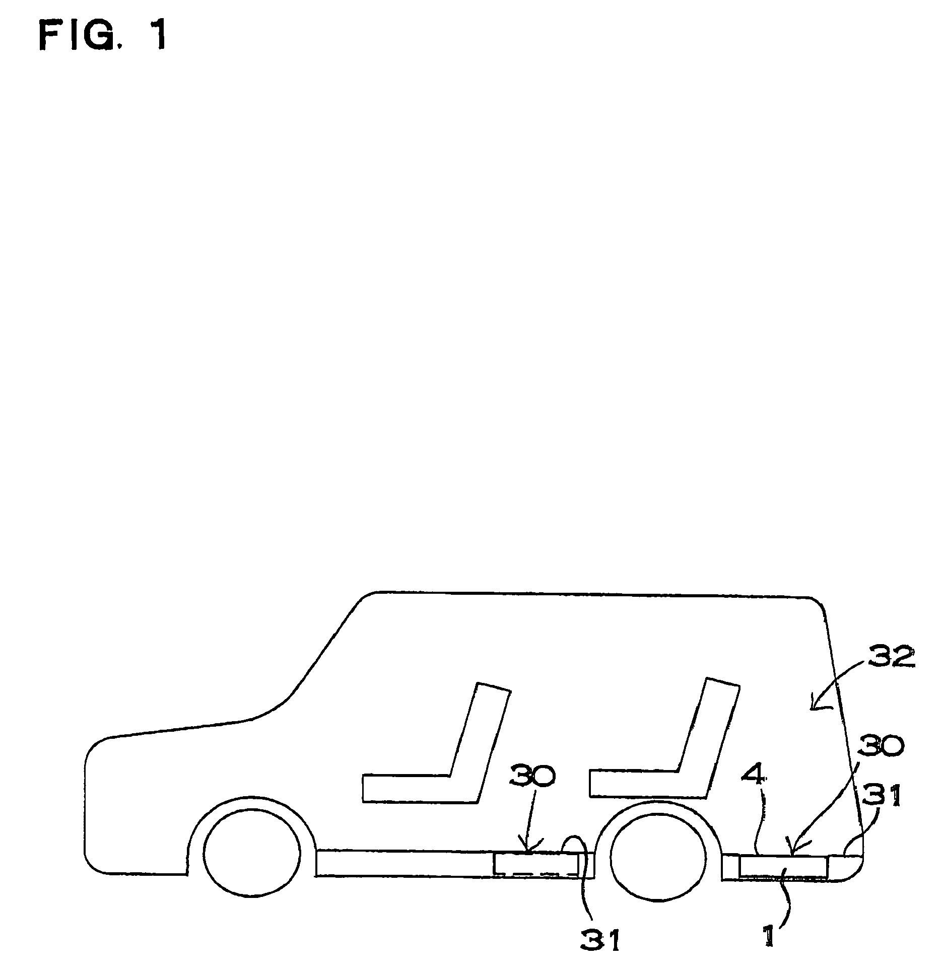
[0057]A vehicle shown in FIG. 1 mounts a power device on a floor 30. The power device to be mounted on the floor 30 of the vehicle is disposed on a loading space 32 provided behind a rear seat as shown in a solid line of FIG. 1 or the floor 30 between the rear seat and a front seat as shown in a chain line, for example. The power device is mounted in such a manner that the upper surface of a case 1 is on the level of a floor panel 31 of the vehicle, and a cover plate 4 fixed to the upper surface of the case 1 can be used as a part of the floor panel 31 of the vehicle. The case 1 sets the cover plate 4 to be a metal plate for bearing the load of the floor panel 31. The power device in which the cover plate 4 bears a load corresponding to a loading of the loading space 32 does not need to support the upper part of the cover plate 4 to withstand a load which is equal to that of the floor panel 31. A concave portion or an opening portion is provided on the floor panel 31 and the power d...


PUM


Abstract

An electric power device for a vehicle has a case that is divided into a first case and a second case. The first case and second case are coupled so as to be separable from each other by the shock of a crash. In the power device, furthermore, a part of the first case and the second case, or a coupling member coupling the first case to the second case, is laminated, and a shock breakage pin to be broken by a predetermined shock penetrates through a laminated portion to couple the first case to the second case.

Description

[0001]This application is based on Application No. 2004-214,929 filed in Japan on Jul. 22, 2004, the content of which is incorporated hereinto by reference.BACKGROUND OF THE INVENTION[0002]1. Field of the Invention[0003]The present invention relates to a power device for driving a motor mounted on a hybrid car or an electric car and causing a vehicle to run.[0004]2. Description of the Related Art[0005]An automobile such as an electric car running by means of an electric motor or a hybrid car running by means of both an electric motor and an engine mounts a power device accommodating a battery in a case. The power device causes the automobile to run by means of an electric motor. In order to increase an output, therefore, a large number of batteries are connected in series, thereby raising an output voltage. For example, a voltage of an electrical battery to be mounted on an automobile is 12V with few exceptions, and the output voltage of the power device for driving a motor for runn...

Claims


Application Information

Patent Timeline
Patent Type & Authority Patents(United States)
IPC IPC(8): B60R16/04
CPCB60R16/04B60L3/0007B60L3/0046B60L50/66B60L50/64B60L58/18B60L58/26Y02T10/70
Inventor FUJII, KAZUHIROHORIUCHI, TATSUHITOSHIMIZU, HIDEOOKADA, WATARU
Owner SANYO ELECTRIC CO LTD
Why Eureka
Try Eureka